
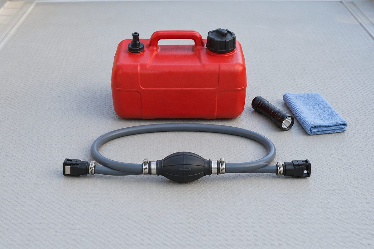
An outboard fuel line and primer bulb inspection before storage can catch leaks, air entry, restriction, and material breakdown before the boat sits for months. The portable or boat-side supply line may look simple, but it includes several sealing points: the hose itself, primer-bulb check valves, clamps, quick-connect fittings, tank pickup, vent, and the engine connection. A small defect can produce hard starting, loss of prime, poor running, fuel odor, or a hazardous leak.
This inspection applies to outboards that use an external primer bulb or detachable tank-to-engine line. Some larger and newer engines prime with an electric pump and may not use a bulb. Mercury, for example, notes that certain FourStroke models 60 horsepower and below use a primer bulb, while 75-horsepower-and-larger models use onboard electric priming. Always follow the engine and boat manuals for the exact configuration.
Treat Fuel Work as a Fire-Safety Task
Work outdoors or in a well-ventilated area away from flames, sparks, hot surfaces, smoking materials, heaters, and equipment that could switch on automatically. Stop the engine, allow it to cool, and turn off unnecessary electrical equipment. Keep an appropriate fire extinguisher accessible.
Wipe up any fuel immediately with an approved absorbent and dispose of it according to local rules. Do not drain gasoline onto the ground, into a bilge, or into the water. If fuel is actively leaking, if the odor is strong, or if you are unsure how to isolate the supply, stop and have a qualified marine technician correct the problem.
Do not pressure-test the line with shop air. A marine fuel system must be tested only by the method and pressure specified by the boat or engine manufacturer.
Identify the Exact Hose Assembly
Before buying parts, record the engine model and serial number, tank type, hose inside diameter, connector style at both ends, and the existing assembly’s part number if legible. Similar-looking connectors are not necessarily interchangeable. Tank systems built under different emissions rules can use different vents, valves, and fittings.
Mercury’s replacement assemblies illustrate why fit matters: the manufacturer lists specific applications, hose diameters, connector types, and compatibility for individual part numbers. Use the engine maker’s parts catalog or an authorized dealer rather than matching only by appearance.
Also note the molded flow arrow on the primer bulb. It must point from the fuel tank toward the engine. Photograph the routing before removal.
Inspect the Hose From Tank to Engine
Yamaha advises checking fuel hoses and connections for leaks or cracking before every trip and using a “sniff test” for fuel odor. During seasonal inspection, examine the entire accessible hose, not just the ends.
Look and feel for:
- surface cracks, splits, cuts, or abrasion;
- hard, brittle, swollen, gummy, or unusually soft areas;
- flattened sections, sharp bends, kinks, or crushing;
- blistering or separation between hose layers;
- dampness, staining, or persistent fuel odor;
- chafe where the hose crosses a hatch, deck edge, rigging tube, or moving engine part;
- unsupported weight hanging from a fitting; and
- damage from heat, sunlight, chemicals, or rodents.
Replace a suspect hose assembly rather than taping, splicing, or coating a damaged section. Use marine fuel hose of the type, diameter, permeation rating, and fire resistance specified for the boat and engine. Ordinary automotive hose is not an automatic substitute.
The line should have gentle bends and enough slack for full steering and trim movement without rubbing, stretching, or entering the water. It should not be used as a handhold, step, or tie-down.
Check the Primer Bulb
Inspect the bulb for cracks, cuts, weather checking, swelling, hardening, softness, or a sticky surface. Check the necks where the hose and clamps load the rubber. Confirm the arrow points toward the engine and that the bulb is routed as the engine manufacturer specifies.
With the system connected and the tank vent set correctly, squeeze the bulb using the starting procedure in the engine manual. Yamaha says that a bulb that does not become firm may indicate a fuel-system leak; if no leak is found, the bulb should be replaced. Mercury likewise describes squeezing until the bulb becomes firm on applicable models.
A bulb that collapses while the engine runs can indicate a restriction upstream, such as a closed or blocked vent, damaged tank pickup, kinked hose, restricted connector, anti-siphon-valve issue, or contaminated filter. A bulb that never firms may point to an air leak, stuck check valve, empty tank, incorrect connection, or failed bulb. These symptoms require diagnosis; they are not a reason to install a stronger clamp or keep pumping indefinitely.
Do not infer bulb condition from softness alone when the engine is off. Temperature, orientation, and system design affect how it feels. Use the manufacturer’s functional test and inspect for leaks.
Inspect Clamps and Hose Ends
Check every clamp for corrosion, broken bands, stripped screws, sharp edges, or movement. The clamp should be the correct type and size, centered over the fitting’s barb, and tightened to the manufacturer’s requirement. Over-tightening can cut a hose or deform a fitting; under-tightening can admit air or release fuel.
Look closely at the hose immediately beside each clamp. A hose end can crack where the rest of the line appears sound. If the manufacturer permits reuse of a fitting, cut back or replace the hose only according to the service instructions. Do not shorten the line until it can no longer accommodate steering and trim travel.
Some factory assemblies use crimped sleeves rather than serviceable clamps. Do not substitute a worm-drive clamp or rebuild a crimped assembly unless the manufacturer authorizes it.
Test Quick-Connect Fittings
Disconnect and reconnect the tank and engine fittings using the manual’s procedure. They should latch positively without excessive force. Inspect the body, release mechanism, O-rings, seals, and fuel valve for cracks, nicks, corrosion, dirt, or deformation.
After reconnection, pull gently to confirm the latch is engaged; do not yank the hose. Support the connector body rather than twisting the hose. A fitting that feels loose, leaks, will not latch, or needs to be held at an angle should be replaced with the correct part.
Keep caps or plugs clean and install them when the manual specifies. Do not insert picks, screwdrivers, or shop-air nozzles into a fuel connector. These can damage the valve or seal.
Check the Tank, Vent, and Pickup Side
A portable tank is part of the same fuel-delivery system. Inspect it for swelling, cracks, impact damage, corrosion, a damaged cap, degraded gasket, loose pickup, or fuel around the outlet. Follow the tank maker’s venting and storage instructions. Some tanks use manual vents; others are designed around pressure-relief and demand-valve systems.
Never modify a cap, vent, demand valve, or connector to cure a priming problem. A closed vent can restrict flow, while an uncontrolled opening can release vapors or fuel. Confirm the correct operating position and replace defective parts by application.
If the boat has a permanently installed tank, inspect the accessible line and connector but do not improvise repairs to the pickup, anti-siphon valve, or below-deck plumbing. Those components may be subject to boat-specific standards and access procedures.
Decide Whether to Store the Line Connected
There is no universal rule for leaving a detachable line connected during storage. Follow the engine, tank, hose, and boat manuals. A procedure may require disconnecting the portable tank, relieving pressure in a particular way, sealing connectors, or leaving treated fuel in selected engine components. Another system may require different steps.
Do not run an injected outboard dry unless its manufacturer specifically directs that procedure. Fuel can cool and lubricate system components, and some engines use electric pumps or vapor-separator tanks that are not emptied by disconnecting the external line.
Use the fuel stabilizer, dosage, and distribution procedure specified by the engine manufacturer. Yamaha’s winterization guidance, for example, describes running an approved treated-fuel mixture through a specific four-cylinder outboard procedure. That is not a generic recipe for every engine.
Replace by Specification, Not Appearance
When replacement is necessary, match all of the following:
- engine family and serial-number range;
- tank and engine connector types;
- hose inside diameter and length;
- approved hose construction and permeation rating;
- primer-bulb orientation and flow direction;
- clamp or crimp method; and
- compatibility with the fuel and emissions system.
Mercury’s current assemblies use application-specific low-permeation hose and defined connectors; its primer-bulb listings also specify the compatible hose diameter. Other engine brands have their own parts. Mixing parts can create a connection that appears to latch but does not seal or flow correctly.
Perform a Leak and Prime Check
After service, move the boat to a safe, ventilated test area. Reconnect the correct tank, open or set the vent as specified, and prime the system only by the engine manual’s procedure. Watch and smell at every connection while the bulb firms.
Start the engine only with the approved cooling-water supply and the boat secured. Observe the hose through idle and, if the manual permits, through steering and trim movement. Shut down immediately for leakage, strong odor, a collapsing bulb, erratic running, or a connector that moves.
Never use a flame to find a leak. Do not continue running to “see if it clears” when fuel is visible or odor intensifies.
Pre-Storage Checklist
- Confirm the engine’s priming method and storage procedure.
- Inspect the entire hose for cracks, softening, hardening, chafe, kinks, and odor.
- Check the primer bulb, molded flow arrow, necks, and functional firm-up test.
- Inspect clamps or crimps at every hose end.
- Disconnect, inspect, and positively re-latch both quick-connect fittings.
- Inspect the portable tank, cap, outlet, pickup, and vent controls.
- Correct hose routing for full steering and trim travel.
- Replace damaged components with application-specific marine parts.
- Complete the manufacturer-approved leak and prime test.
- Store the tank and line exactly as their manuals and local rules require.
Record the Inspection in BoatDuty
Record the date, engine hours, engine model and serial number, hose assembly part number, hose diameter and length, tank type, primer-bulb part number, observed symptoms, replaced clamps or connectors, and the result of the prime and leak checks. A photo of the flow arrow and routing is especially useful.
Adding the service to BoatDuty creates a practical reference when the line needs replacement again or when a hard-start complaint appears next season. The record should describe what was actually inspected and tested—not merely say “fuel system checked.”
Sources
- Yamaha Outboards, “Fuel & Fuel System Maintenance” (hose, connection, leak, odor, and primer-bulb checks)
- Yamaha Outboards, “Gasoline Basics” (regular fuel-hose and primer-bulb inspection)
- Yamaha Outboards, “How to Winterize Your 4-Cylinder Outboard” (model-specific treated-fuel procedure)
- Mercury Marine, “Quick Tip: Priming Your Fuel System” (primer-bulb operation and electric-priming distinction)
- Mercury Marine, fuel-line assembly 8M0061897 (application, low-permeation hose, diameter, and connector details)
- Mercury Marine, primer bulb 8M0052976 (hose-diameter and component-fit details)