

Marine holding-tank vent maintenance before storage is a small job with an outsized effect on odor control, pump-out performance, and tank health. The vent line lets displaced air leave as the sanitation tank fills and lets air return while the tank is pumped out. If the hose, fittings, through-hull, or odor filter becomes restricted, the system can pressurize or pull a vacuum instead of breathing freely.
Not every boat has the same arrangement. Some holding tanks vent directly through the hull; others include an activated-carbon filter, a large-diameter vent, or more than one vent. A tank vent is also different from a vented anti-siphon loop in a toilet inlet or discharge hose. Map the actual sanitation system, use the tank and filter manuals, and follow local pump-out and waste-handling rules before starting.
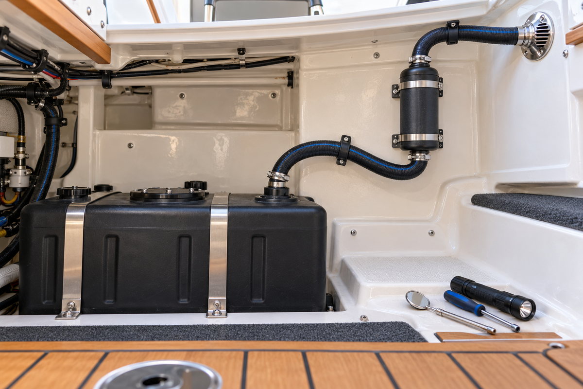
What the holding-tank vent does
Air must move both ways through a sanitation-tank vent:
- out of the tank as flush water and waste enter; and
- into the tank as a dockside pump-out removes the contents.
The vent usually starts at a fitting on the upper portion of the tank and runs to a hull fitting high above the waterline. A filter, when fitted, sits in that route. Jabsco's Type III waste-system manual, for example, connects the tank vent to an outlet high on the hull near the gunwale. VETUS instructs installers of its No-Smell filter to locate the unit above the waterline in a dry, cool, accessible place and high enough to keep liquid or foam out.
Vent design is not interchangeable across boats. Hose diameter, allowable filter restriction, routing, and the number of vents must match the tank and equipment documentation. Never reduce a vent line simply to fit a convenient filter.
Warning signs of a restricted sanitation vent
Investigate the vent path if you notice:
- a toilet that becomes harder to flush as the tank fills;
- unusual pressure or a rush of air when a cap or fitting is opened;
- odor that suddenly worsens at the vent outlet or inside the boat;
- slow or incomplete dockside pump-out;
- the tank visibly swelling during use or drawing inward during pump-out;
- liquid or foam reaching the vent filter;
- a vent hose that stays wet in a low spot; or
- a through-hull screen blocked by salt, insects, debris, or dried residue.
These symptoms are clues, not proof of one failure. A full tank, bad level sender, restricted discharge hose, failing toilet valve, or pump-out equipment problem can produce overlapping symptoms. Diagnose the complete system rather than replacing the odor filter by default.
Prepare the system safely
Pump the holding tank at an approved facility before opening sanitation plumbing. Rinse and empty it as the boat and toilet manufacturers direct. Isolate electrical equipment that could start automatically, close relevant seacocks, ventilate the compartment, and use appropriate eye protection and chemical-resistant gloves during the physical work. This article's inspection image intentionally contains no people or protective equipment; use the protection required for the actual service.
Keep absorbent material, a capped catch container, disinfectant approved for the boat's materials, and replacement clamps or plugs ready. Do not use an open flame, and never blow through a sanitation hose by mouth. Avoid compressed air unless the tank manufacturer provides a specific low-pressure procedure; an unregulated air source can damage a tank or force contaminated material out of another opening.
Trace and label the complete vent route
Find the tank's vent fitting and physically follow the line to the hull outlet. Do not confuse it with the larger deck pump-out hose, a toilet discharge line, or a vented loop. Photograph the installation before disturbing it.
Record:
- tank make and model;
- vent fitting location and nominal size;
- hose inside diameter and material markings;
- filter make, model, orientation, and element date;
- through-hull style and location;
- clamp count and type at each connection; and
- routing details, supports, high points, and low points.
If the hose disappears behind joinery, identify both ends and every accessible section. A hidden sag can hold condensate or liquid even when the visible run looks correct.
Inspect the tank fitting and hose connections
With the system empty, inspect the tank around the vent fitting for cracks, staining, softened material, movement, and leakage. Verify that the fitting is secure without twisting or side-loading the tank wall. Do not tighten a plastic fitting by feel alone; use the tank manufacturer's method and torque if specified.
At every hose connection, look for:
- a clamp that is loose, corroded, cutting the hose, or positioned off the barb;
- cracked or swollen hose ends;
- a hose that has hardened and no longer seals evenly;
- sharp bends, kinks, or crushing behind a bulkhead;
- chafe where the line crosses an edge; and
- residue that suggests liquid reached a connection.
Use the clamp arrangement required by the equipment manual. VETUS's NSF filter instructions specify flexible hose at both filter connections and one stainless-steel hose clamp per connection for that product. That is not permission to change the clamp count on a different tank, fitting, or filter.
Correct sags, loops, and unsupported hose
For its No-Smell filter, VETUS directs the vent line to slope downward from the filter to the tank and to be supported well enough to prevent sagging or a siphon. This routing helps keep moisture, foam, and tank contents out of the activated-carbon element.
Inspect every support clip. Replace broken clips with compatible hardware, protect the hose from sharp edges, and maintain the bend radius specified for the hose. Do not create a low pocket simply to make the line look tidy. On sailboats, assess routing at normal heel angles as well as at the dock.
If the existing installation contradicts the equipment manual, document it before modifying anything. A qualified marine sanitation technician can determine whether rerouting, a different filter position, or a larger vent is appropriate.
Check the through-hull vent fitting
Inspect the exterior vent only when the boat is safely accessible. Remove surface debris without forcing it deeper into the line. Check for a bent cover, blocked screen, insect nest, salt crystals, corrosion, or sealant failure around the fitting. From inside, confirm that the hose is secure and that the fitting is not leaking into the hull.
Screens and flame-arresting elements are not universal. Do not remove a factory component permanently just because it collects debris; clean or replace it according to the fitting manufacturer's instructions. Likewise, do not push a drill bit, wire, or high-pressure nozzle through an unknown vent path. It could damage the hose or filter and drive contamination back toward the tank.
Service an activated-carbon vent filter correctly
An odor filter is a service item, not a permanent canister. Activated carbon captures selected odor molecules, but moisture and contamination reduce its effectiveness. VETUS states that its NSF element should be replaced at least annually at the start of the season, or when its silica gel is saturated, and always if liquid or foam has entered the filter. The company also calls for annual inspection of the vent line and fittings for blockage or damage.
Those intervals apply to that VETUS product. Other filters may have a different element, service life, orientation, disposal method, or no field-serviceable media at all. Use the correct replacement element and date the service. Do not refill a sealed housing with aquarium carbon or improvised media unless the manufacturer explicitly authorizes it.
When removing a filter:
- Confirm that the tank is empty and not pressurized.
- Mark the hose routing and any flow direction shown on the housing.
- Support the hoses so they do not pull on the tank or through-hull.
- Cap open lines temporarily to control odor and prevent dropped debris.
- Inspect the housing, brackets, seals, and hose barbs.
- Install the specified element and service seals only with the approved lubricant.
- Reconnect the hose without kinks and restore every support.
VETUS warns that a filter adds resistance to the vent line and that, during dockside suction pump-out, inadequate airflow can allow a waste tank to collapse. This is a strong reason to stop a pump-out if the tank begins to deform or airflow seems abnormal. Do not treat a carbon filter as harmless plumbing.
Verify airflow without overpressurizing the tank
The safest test method is the one specified by the tank or sanitation-system manufacturer. A visual inspection may be followed by a controlled check with the filter disconnected and the tank empty, but do not improvise with shop air.
Before reassembly, confirm that each removable hose section and the exterior fitting are unobstructed using an approved low-pressure method. Reconnect the complete system, then check for leaks and secure routing. During the next normal flush and pump-out, monitor the tank and vent:
- the tank should not visibly balloon or collapse;
- air movement should not be accompanied by liquid at the vent;
- connections should remain dry; and
- the pump-out should proceed normally without the tank deforming.
If a blockage cannot be located, or if the tank has deformed, stop using the system and arrange professional service. A distorted polyethylene tank may not safely return to its original strength or shape.
Prepare the vent system for winter storage
The vent line is only one part of sanitation winterization. Pump, rinse, drain, and protect the toilet, tank, pumps, valves, discharge plumbing, and seacocks using their individual manuals and a winterization method suitable for the expected temperature. Do not assume that pumping the tank empty removes water from every hose or low point.
For the vent path:
- leave the through-hull clear and externally protected only in a way that still permits required ventilation;
- eliminate trapped liquid in sags or low sections;
- keep a serviceable carbon element dry;
- replace any filter that has been wetted, if its manual requires replacement;
- secure loose hoses and brackets; and
- note any repair that must be completed before the system is recommissioned.
Never seal a holding tank airtight for storage unless the tank manufacturer explicitly instructs it. Temperature changes and residual biological activity can change internal pressure.
Holding-tank vent maintenance checklist
- Pump out, rinse, and empty the tank according to the system manual.
- Trace the vent from tank fitting to hull outlet.
- Distinguish the tank vent from vented anti-siphon loops.
- Inspect the tank fitting, hose ends, clamps, and supports.
- Correct kinks, chafe, unsupported spans, and liquid-trapping sags.
- Clean the exterior vent fitting without pushing debris inward.
- Inspect the filter housing, element, seals, brackets, and flow orientation.
- Replace the element on the manufacturer's schedule or after contamination.
- Verify unobstructed airflow by an approved low-pressure method.
- Monitor tank shape and connections during the next flush and pump-out.
- Record all parts, sizes, dates, observations, and deferred repairs.
Record the service in BoatDuty
Use BoatDuty to log the pump-out and inspection date, tank model, vent hose size, filter model and element part number, through-hull style, clamps replaced, and the method used to confirm airflow. Add photos of routing and filter orientation before service. Record whether the element was dry, moisture-saturated, or contaminated by liquid, and note any tank deformation or pump-out symptom that requires follow-up.
That history helps separate an isolated odor event from a recurring restriction. It also prevents a forgotten filter element from remaining in service for multiple seasons.
The practical takeaway
A holding tank needs a clear, correctly sized path for air in both directions. Inspect the full route—not just the odor filter—before storage. Keep the hose supported, the through-hull open, the filter dry and current, and the tank free from pressure or vacuum. When routing or airflow does not match the manual, correct the cause before the next flush or pump-out.