

A marine generator can start instantly at the dock yet still fail when several real loads are applied. Long periods of light or no-load operation may not bring a diesel to healthy operating temperature, while a gasoline genset can hide cooling, ignition, or fuel-delivery faults until demand rises. A controlled marine generator exercise and load test before storage creates a useful operating baseline and exposes problems while service access is still available.
This is not a universal instruction to connect a portable load bank or probe live terminals. Generator size, fuel, cooling system, governor, voltage, frequency, transfer equipment, and control logic vary widely. Follow the exact operator manual. Owners can perform documented pre-start checks and operate normal onboard loads when the installation and manuals permit. Exposed AC measurements, internal adjustments, insulation tests, load-bank connections, and fault simulation belong to a qualified marine generator technician.
Carbon monoxide is odorless and deadly. Never run a generator in an enclosed building, under a storage cover, beside an occupied boat, or where exhaust can enter cabins or nearby structures. Confirm ventilation, exhaust discharge, carbon-monoxide alarms, cooling-water supply, and safe clearances before every run.
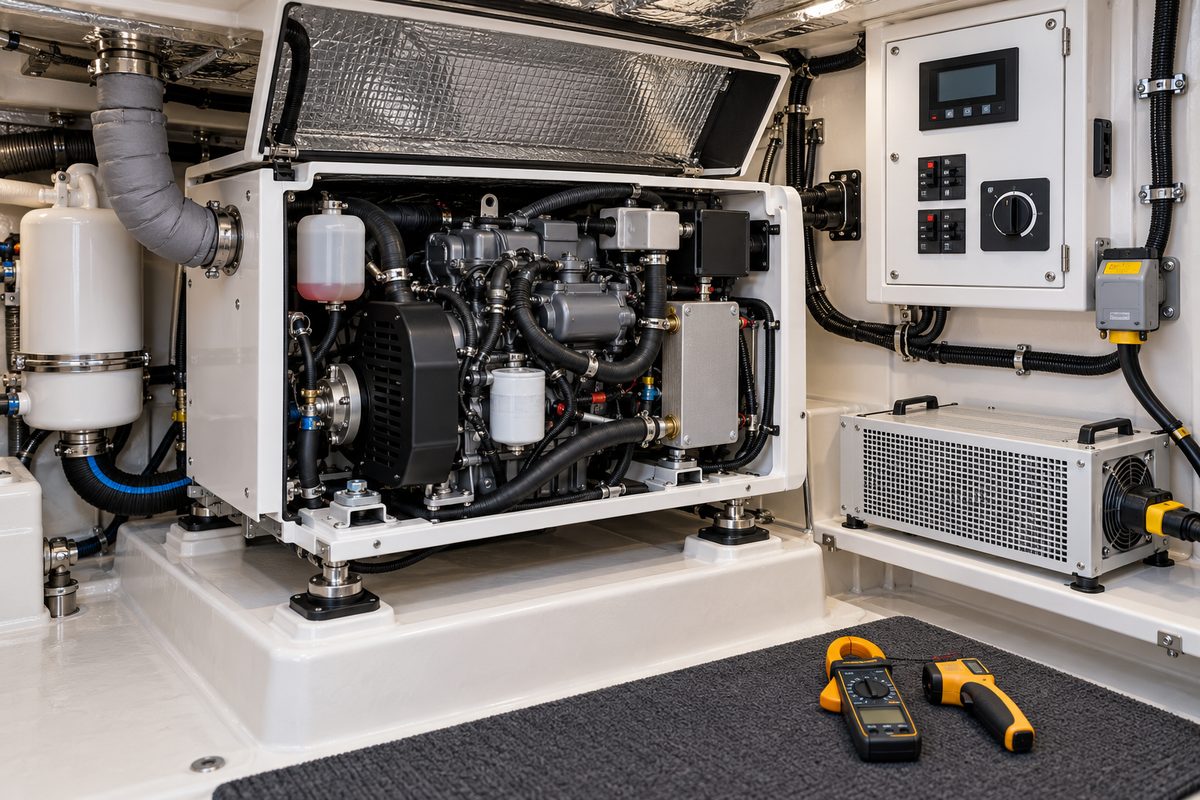
Know What the Generator Exercise Is Supposed to Prove
Exercise is more than starting the engine for a few minutes. The useful test confirms that the complete set can:
- crank and start normally from every intended station;
- establish raw-water flow and stable cooling;
- reach normal oil pressure and operating temperature;
- carry a meaningful, controlled electrical load;
- maintain acceptable voltage and frequency;
- transfer loads correctly without paralleling shore and generator sources;
- respond to load changes without stalling, hunting, smoking, or overheating;
- stop normally and record no unresolved fault; and
- cool down and remain leak-free after shutdown.
Cummins Onan’s current marine operator guidance for applicable models says to exercise an infrequently used set at least one hour per month at roughly one-quarter to three-quarters load and to minimize no-load operation. Westerbeke publishes its own model-family exercise procedures. Use those intervals and load targets only for the generator to which they apply.
Identify the Generator and All Connected Systems
Record:
- manufacturer, model, specification letter, serial number, fuel, and rated output;
- rated voltage, phase, and frequency;
- engine and generator hours;
- coolant and oil specifications;
- raw-water intake, strainer, pump, heat exchanger, siphon break, exhaust hose, waterlift muffler, and outlet;
- start battery, charger, fuse, switch, and remote stations;
- generator main breaker and source selector or automatic transfer switch;
- circuits normally carried by the genset;
- automatic generator-start equipment; and
- recent shutdown codes, warnings, voltage or frequency complaints, smoke, odor, or cooling symptoms.
Find the operator manual by the full model and specification, not merely the brand and kilowatt rating. Two visually similar units can use different controllers, oil, coolant, service intervals, and fault logic.
Prepare for a Safe, Meaningful Test
Choose an open, well-ventilated location where exhaust cannot be trapped. Remove the boat’s storage cover. Check that nearby boats, docks, doors, windows, and people will not be exposed to exhaust. Test installed carbon-monoxide alarms by their manufacturer’s procedure before running.
For gasoline boats and generators, operate the blower and ventilate for the boatbuilder’s prescribed time. Sniff tests do not replace vapor controls. Stop if a fuel-vapor detector alarms or if fuel odor is unexplained.
Disconnect shore power or place transfer equipment in the required position according to the boat’s source-selection procedure. A compliant selector or transfer device must prevent shore power and generator output from being interconnected. Never backfeed a shore cord, household receptacle, or another panel.
Turn off large loads before starting so the engine can stabilize. Disable automatic generator start while inspecting or servicing. Restore it only if the final storage plan requires it and the entire system is approved for unattended operation.
Complete the Manual’s Pre-Start Checks
With the generator stopped and cool:
- check engine oil at the specified condition and dipstick procedure;
- inspect coolant level only at the approved tank or recovery bottle;
- confirm raw-water seacock position and strainer condition;
- inspect belts, guards, hoses, clamps, mounts, and wiring;
- look beneath the set for fuel, oil, coolant, or seawater;
- check the exhaust hose, waterlift muffler, drain plug, and outlet;
- verify the start battery is secure and charged;
- clear tools, rags, spare parts, and gear from air inlets and hot surfaces; and
- confirm the generator breaker and onboard loads are in their required start positions.
Do not open a hot pressure cap. Do not run the raw-water pump dry. If winterization has already removed the impeller, drained the cooling system, disconnected the battery, or introduced antifreeze by a storage-only setup, recommission the system exactly as the manual requires before any test.
Observe the Start Sequence
Start from the local control first unless the manual specifies otherwise. Note crank time, number of attempts, smoke, unusual sound, vibration, and the time required for oil-pressure and charging indications to normalize.
Confirm prompt cooling-water discharge at the exhaust. The appearance varies by exhaust design and speed, so compare with the boat’s normal baseline. Little or no water, steam, a sharp exhaust-note change, a rising temperature indication, or an alarm requires immediate shutdown.
Let the set warm at the manual’s recommended no-load or light-load period. Avoid extended idling. Cummins warns that prolonged no-load operation can lower diesel cylinder temperature enough to cause incomplete combustion, fuel wetting, and white smoke.
Walk around the installation without touching hot or moving parts. Check:
- raw-water and coolant hose joints;
- fuel filters, lines, pumps, and return connections;
- oil filter and drain hose;
- exhaust elbow, hose, waterlock, and outlet;
- mounts and sound enclosure;
- battery cables and harnesses; and
- air intake and ventilation path.
Stop for active leakage, arcing, burning odor, metallic knock, severe vibration, exhaust entering the boat, or a safety alarm.
Apply Normal Onboard Loads in Controlled Steps
The safest owner-level exercise usually uses installed loads that the boat’s electrical design assigns to the generator. Examples may include a water heater, battery charger, cooktop element, air conditioner, or other resistive and motor loads. Not every boat has these loads, and not every combination is acceptable.
Build a written load plan from nameplate ratings and normal operating current. Start with a modest stable load, then add one load at a time. Allow the generator to stabilize after each step. Watch for motor starting surges; an air conditioner or pump can demand much more current at startup than while running.
Do not use damaged appliances, temporary extension cords, improvised heater banks, or portable equipment in wet machinery spaces. Do not exceed the generator’s rating or the branch, transfer, and shore-selector ratings.
At each step, record:
- total indicated load or estimated amperage;
- AC voltage and frequency from installed meters;
- engine temperature and oil-pressure indication;
- exhaust-water flow;
- sound, vibration, smoke, and odor;
- controller warnings; and
- whether a newly started load causes excessive voltage or frequency dip.
Westerbeke’s current gasoline-generator manual describes a model-specific load test that progresses from no load to half capacity and then full rated capacity while voltage and load are monitored. That is useful only when performed under the applicable manual and safe measurement conditions. Owners should not imitate a full-output test without confirming that the boat’s wiring and loads can support it.
Distinguish Onboard Exercise From a Professional Load-Bank Test
An onboard load exercise proves that the boat’s normal equipment can be powered. It may not reach or hold the generator at a precise percentage of rated output. A load bank is specialized equipment that applies a controlled electrical demand and allows technicians to measure performance across a planned profile.
Professional load-bank testing may be warranted when:
- the boat lacks enough reliable onboard load;
- a diesel has a history of prolonged light-load operation or wet stacking;
- voltage or frequency becomes unstable as load rises;
- the set trips below its expected capacity;
- a major engine, governor, alternator, or controller repair was completed;
- the generator has been stored for an extended period;
- smoke persists after normal warmup and service; or
- reliable full-output performance is critical.
Cummins explains that load banks verify performance under controlled demand and can help address wet-stacking risk in lightly loaded diesels. A marine technician must choose the equipment, connection point, cable protection, ventilation, test duration, and loading sequence. Do not connect a rental load bank directly to a boat panel without a designed, protected interface.
Monitor Voltage and Frequency Safely
Voltage and frequency depend on generator design, speed, electronic controls, and load. Use installed digital displays or meters when available. A plug-in meter may be appropriate only at a correctly wired, dry, protected receptacle and within its rating.
Never remove an energized cover to place meter probes on a terminal. Clamp meters measure current only when used on the correct individual conductor, not around a complete cable containing outgoing and returning conductors. Exposed AC measurement and adjustment require trained personnel, insulated tools, rated instruments, personal protective equipment, and safe access.
Record values instead of immediately changing governor or regulator settings. Low frequency may reflect engine-speed or fuel problems; low voltage can involve regulation, excitation, overload, connection resistance, or speed. Adjusting one system to conceal another fault can cause appliance damage.
The acceptable range is generator- and load-specific. Compare readings with the operator manual and prior documented tests, not with a generic internet target.
Watch the Cooling and Exhaust Systems Under Load
Heat rejection rises as electrical load increases. A set that runs indefinitely at idle may overheat under real demand if the intake, strainer, impeller, exchanger, siphon break, mixing elbow, exhaust hose, or waterlock is restricted.
During the test, observe:
- stable temperature indication;
- consistent cooling-water discharge;
- no steam or scorched-rubber odor;
- no seawater leakage at hoses, clamps, drains, or pump;
- no coolant seepage or recovery-bottle overflow;
- a dry exhaust-hose exterior with no soft, bulged, or discolored area;
- secure sound shield and mounts; and
- no exhaust gas or carbon-monoxide alarm inside occupied spaces.
Never touch an exhaust elbow or hose to judge temperature. A technician may use a contact probe or infrared camera at documented points, but surface temperature alone does not prove internal water flow or hose condition.
Evaluate Engine Behavior and Combustion Clues
As load rises, the engine should accept demand without prolonged hunting, misfire, stalling, or abnormal smoke. A brief transient may be normal for a particular mechanical governor, while an electronically controlled set may recover differently.
Persistent black smoke can indicate overload, restricted air, fuel-system problems, or combustion faults. White smoke after warmup can indicate incomplete combustion, low cylinder temperature, coolant, or fuel problems. Blue smoke can indicate oil burning. These colors are clues, not diagnoses.
Do not keep loading a smoking or unstable generator in hopes that it will “clear out.” Confirm fuel quality, filters, air path, exhaust restriction, injectors or ignition, compression, and governor control through the manufacturer’s diagnostic process.
Test Transfer, Controls, and Shutdown Behavior
After the generator is stable under load, confirm the boat’s source-control behavior by the manual. A selector or automatic transfer switch must never parallel an ordinary marine generator with shore power unless the system was specifically engineered for synchronized operation.
Check that:
- generator power reaches only intended circuits;
- reverse-polarity or leakage-protection devices do not show a fault;
- the transfer occurs in the expected sequence;
- high-demand loads remain managed as designed;
- local and remote stop controls function; and
- the controller records no unresolved warning.
Do not simulate low oil pressure, over-temperature, overspeed, or loss of cooling by disconnecting sensors or starving the engine. Cummins suggests fault simulation only where the model procedure and qualified service conditions support it. A technician can use approved test modes and diagnostic software without defeating safety systems.
Before normal shutdown, remove loads in the recommended sequence and allow the manual’s cooldown period. Westerbeke’s published exercise guidance for applicable models includes a short no-load or very-light-load cooldown. Then stop the set and turn off the generator breaker if the storage procedure requires it.
Inspect Again After Shutdown and Cooldown
Remain alert for hot surfaces and stored electrical energy. Once safe, inspect for fresh coolant, seawater, oil, or fuel. Check the bilge, drip tray, hose joints, filter bases, drain hose, exhaust connections, and recovery bottle.
Note any hot-electrical odor, discolored cable, breaker trip, loose mount, or new soot. Recheck fluid levels only at the manual’s stated condition. Some coolant level changes are normal after heat cycling; an unexplained drop is not.
Review controller history before clearing faults. Record the exact code, operating hours, load, and circumstances. A fault erased without context is harder to diagnose in spring.
Put the Generator Into the Correct Storage State
Generator storage procedures are model- and climate-specific. They may address oil and filter service, fuel stabilization or fuel-system preservation, coolant freeze protection, raw-water draining or antifreeze, impeller removal, waterlift muffler drainage, battery storage, corrosion protection, and control settings.
This article’s exercise test does not replace those procedures. Complete due service by hours and calendar interval, then follow the generator manual’s storage section. Do not leave the set available for automatic start after cooling water has been isolated or the exhaust system drained.
Tag the generator with:
- date of last exercise and hours;
- maximum tested load;
- oil, coolant, fuel, or filter service completed;
- drains, impeller, hoses, or battery disconnected;
- breaker and seacock positions;
- unresolved faults; and
- exact recommissioning steps.
Spring Recommissioning
Review the storage record before moving any control. Reinstall drains, plugs, impeller, battery connections, and exhaust components exactly as documented. Confirm coolant and oil, open the seacock, ventilate, and perform the pre-start check.
Start with loads off, verify cooling flow, and inspect for leaks. Repeat a controlled onboard load test before depending on the generator away from the dock. Compare voltage, frequency, temperature, start time, and load acceptance with the fall baseline.
Marine Generator Exercise and Load-Test Checklist
- Identify the exact generator model, specification, rating, and manuals.
- Review hours, service intervals, fault history, and recent symptoms.
- Remove covers and confirm exhaust cannot enter any occupied space.
- Test CO alarms and ventilate gasoline spaces by the boat procedure.
- Verify shore/generator isolation and disable automatic start for inspection.
- Check oil, coolant, raw-water intake, hoses, belts, exhaust, battery, and leaks.
- Start with loads off and confirm prompt cooling-water flow.
- Warm up only for the time specified; avoid extended no-load running.
- Add normal onboard loads in planned steps without exceeding ratings.
- Record load, voltage, frequency, temperature, smoke, noise, and faults.
- Stop for leakage, overheating, arcing, exhaust intrusion, or instability.
- Use a qualified technician for exposed AC tests or formal load-bank work.
- Remove load, cool down, stop, and inspect again.
- Complete the model-specific storage procedure and tag every altered state.
- Repeat the controlled test during spring recommissioning.
Record Generator Maintenance in BoatDuty
Create a BoatDuty entry with generator model, specification, serial number, hours, start time, ambient conditions, fuel, oil and coolant specifications, service performed, load steps, maximum load, voltage and frequency at each step, temperature indication, exhaust-water observations, smoke or vibration, controller faults, remote and transfer-test results, cooldown time, repairs, technician, and final storage configuration.
The value is in the trend. If next season’s generator takes longer to start, carries less load, runs hotter, or shows a larger frequency dip, a detailed BoatDuty history makes that change visible before it becomes a shutdown away from the dock.
Sources
- Cummins Onan, Marine Generator Set Operator Manual, MDKBJ–MDKBW, July 2024 (loading, no-load operation, and monthly exercise guidance)
- Cummins Onan, Marine Generator Set Operator Manual, MDKBH, July 2024 (model-specific operation and maintenance schedule)
- Cummins, Onan Marine Generator Maintenance (pre-trip checks, loaded operation, extended storage, and recommissioning)
- Cummins, Load Bank Performance Testing (controlled generator loading and wet-stacking considerations)
- Westerbeke, Marine Generator Maintenance FAQs (model-family exercise procedures and cooldown guidance)
- Westerbeke, 15.0–23.0 MEG Gasoline Generator Operator Manual (model-specific progressive load test and voltage/load monitoring)
- Westerbeke, 7.5 MCGB Multiport EFI Product Support (current January 2026 operator-manual access for applicable models)