

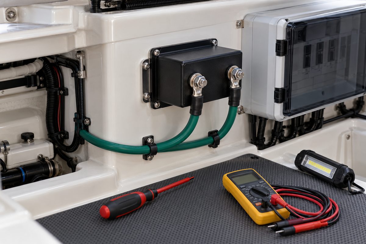
A marine galvanic isolator works quietly in one of the boat’s most important safety circuits. Installed in series with the incoming AC safety-grounding conductor, it is designed to block the low-voltage DC currents that contribute to galvanic corrosion while still providing a path for AC fault current. Because the device is connected to the green grounding conductor—not an optional accessory wire—inspection must protect both corrosion control and shock safety.
End-of-season layup is a useful time to document the isolator, inspect its environment and connections, and follow its model-specific test procedure. It is not the time to bypass the device, disconnect the safety ground, or improvise a diode test from an unrelated internet diagram. Boats with isolation transformers, monitored isolators, fail-safe isolators, or multiple shore-power inlets can require very different checks.
What a Galvanic Isolator Does—and Does Not Do
When boats are connected to a marina’s shore-power system, their AC safety-grounding conductors can create a low-voltage DC path between underwater metals. A galvanic isolator raises the threshold that this small DC galvanic current must overcome. Victron describes the basic device as opposing diode paths that block low-voltage DC while conducting when a sufficiently higher voltage appears. Blue Sea Systems similarly defines it as an inline device on the AC grounding conductor that blocks galvanic current but permits AC grounding current.
That function has firm limits:
- It does not replace sacrificial anodes, correct bonding, sound shore-power wiring, or an investigation of stray current.
- It does not correct a leaking DC circuit, a damaged AC appliance, or a marina wiring fault.
- It does not protect an unplugged boat from every source of corrosion.
- It is not the same as an isolation transformer, which separates the boat’s AC supply from the shore-side circuit by transformer action.
Rapid anode loss, underwater-metal damage, or a tingling sensation near a boat demands prompt professional diagnosis. Never enter the water around a boat or dock where electrical leakage is suspected.
Identify the Device and the Shore-Power Configuration
Before touching anything, record the isolator’s manufacturer, model, serial number, current rating, certification markings, installation date, and whether it has a separate monitor. Confirm how many shore-power inlets the boat has and whether each relevant grounding conductor passes through the intended device.
Ratings must match the installation. ProMariner currently offers ProSafe FailSafe models for 30- and 50-amp shore-cord applications, while other manufacturers use different rating conventions for 120- or 230-volt systems. A physically similar enclosure is not proof that the isolator is correctly sized.
Some boats use an isolation transformer instead of a galvanic isolator. Others have generator and inverter/charger transfer systems that change how neutral and grounding conductors behave. Do not add, remove, or relocate an isolator without the boat’s wiring diagram and qualified marine-AC guidance.
De-Energize Every AC Source
Shore power is only one possible source of AC energy aboard. Before opening a panel or approaching exposed terminals:
- Turn off AC loads using the boatbuilder’s sequence.
- Switch off the shore-power main breaker.
- Disconnect the shore cord at the dock pedestal and boat.
- Disable the generator so it cannot start automatically.
- Turn off inverter AC output and automatic transfer functions.
- Apply lockout or warning tags where appropriate.
- Have a qualified person verify absence of voltage with a properly rated tester.
Do not depend on a dark display or an open shore breaker. An inverter, generator, miswired transfer switch, or second inlet may still energize part of the AC system.
If the isolator terminals are exposed, treat inspection and testing as professional work. The safest owner-level inspection may be limited to the sealed enclosure, mounting, accessible cable supports, monitor status, and documentation.
Inspect the Enclosure and Mounting
The isolator should be secured in the location and orientation specified by its manufacturer. Inspect for:
- cracks, swelling, melted areas, discoloration, or a burnt odor;
- water trails, condensation, salt deposits, green corrosion products, or rust stains;
- loose mounting hardware, damaged vibration isolation, or a chafed enclosure;
- blocked ventilation space where the design requires airflow;
- stored gear pressing on the unit or cables;
- fuel, oil, cleaning chemicals, or battery electrolyte nearby; and
- evidence that a cable, hose, or moving component rubs the device.
Do not drill the sealed case or open a potted isolator. Dairyland, for example, describes its marine fail-safe units as sealed, passive devices with no internal maintenance requirement. Other models include monitors or external status wiring that must remain intact.
Water intrusion around the compartment is a system fault even when the isolator itself is sealed. Find and correct the leak, then inspect adjacent AC equipment and grounding connections for contamination.
Check the Grounding Conductors and Terminations
A galvanic isolator is installed in the fault-current path. Both sides therefore deserve the same disciplined inspection as other critical AC grounding connections.
With all sources safely isolated, look for:
- the specified green or green/yellow insulation color;
- correct conductor size for the shore-power service;
- smooth routing without sharp bends, crushing, or unsupported weight;
- secure cable clamps and strain relief near the terminals;
- properly sized, one-hole ring lugs rather than open spade terminals;
- intact heat-shrink or protective boots where specified;
- no exposed strands, cut insulation, overheated copper, or blackened terminals;
- no extra conductors stacked on a stud unless the manual permits them; and
- no alternate wire or metal strap that bypasses the isolator.
Do not “check tightness” by pulling hard on energized or unidentified wiring. Do not apply a generic torque value. Terminal hardware, washer order, lug size, corrosion treatment, and torque come from the exact installation manual. Over-tightening can damage studs or the encapsulated device; under-tightening can create resistance and heat.
If a terminal must be disturbed, the connection should be rebuilt with the specified marine-grade conductor and crimping method, then torque-marked and documented by a qualified technician.
Verify There Is No Grounding-Conductor Bypass
An isolator can be electrically defeated even when it looks perfect. A second shore inlet, cable-TV shield, telephone connection, dock-water bonding path, metal gangway, charger, or undocumented wiring change can create another conductive connection between boat and shore.
Finding parallel paths requires more than a visual glance. A marine electrician may use continuity, clamp-current, or corrosion-potential measurements according to the boat’s configuration. Never remove the AC safety ground to eliminate a suspected bypass. Blue Sea Systems specifically warns that omitting the green safety-grounding connection sacrifices shock protection.
If the boat uses a cable or data connection at the dock, check whether the installation requires an appropriate isolation device. Do not assume that a coaxial connector or metal plumbing fitting is electrically harmless.
Follow the Exact Test Procedure
There is no universal two-probe reading that applies to every galvanic isolator.
Older or non-fail-safe products may require a monitoring system. Certified fail-safe models may not require continuous monitoring but can still provide a field-test procedure. Dairyland states that its units can be field tested with a multimeter and a DC clamp ammeter and includes pre-installation and installed testing steps in its instructions. ProMariner’s manuals and monitor-equipped products use their own procedures.
Before testing, determine:
- whether the unit is fail-safe or non-fail-safe;
- whether a monitor must remain connected;
- whether test leads must be disconnected from the circuit;
- the specified meter function, polarity sequence, and acceptable readings;
- whether shore power must remain disconnected; and
- whether an installed test requires a qualified electrician.
Do not use a household continuity buzzer as the sole pass/fail test. Diode arrays, surge components, monitoring circuits, and parallel grounding paths can make a casual reading misleading. Never energize the system merely to see whether the case gets warm.
Record the actual readings and test configuration, not only “passed.” Trends are useful when the same approved method is repeated over time.
Inspect Any Monitor or Alarm
If the isolator has a monitor, check its power source, display, alarm history, wiring harness, connector security, and model-specific self-test. An extinguished lamp does not necessarily mean the system is healthy; it may indicate lost monitor power.
Investigate any fault indication before reconnecting shore power. Do not silence or disconnect an alarm without correcting the cause. Save the displayed code or lamp pattern in the maintenance record because some indications are difficult to reproduce later.
Look for Related Corrosion Clues
The isolator inspection should be compared with the boat’s broader corrosion history:
- external anode condition and replacement interval;
- pitting or discoloration on underwater metals;
- bonding-wire condition at accessible fittings;
- shore-connected versus unplugged storage patterns;
- recent marina or slip changes;
- additions such as an inverter/charger, air conditioner, or dockside communications cable; and
- underwater potential measurements from a qualified corrosion survey.
Anodes that disappear unusually quickly do not prove the isolator failed. The cause could be a parallel shore connection, DC leakage aboard, incorrect anode alloy, bad bonding, nearby stray current, or a change in water chemistry. Treat the evidence as a system-level diagnostic problem.
Recommission Shore Power Carefully
After inspection or service, verify that terminal covers, boots, cable clamps, panel covers, and compartment barriers are restored. Remove tools and lockout tags only when the system is complete.
Reconnect using the boatbuilder’s shore-power procedure. Observe reverse-polarity, ground-fault, isolation-monitor, or galvanic-isolator indicators before adding loads. Test installed GFCI, RCD, or ELCI devices using their approved test controls and intervals. Gradually restore loads while watching for heat, odor, noise, alarms, or voltage problems.
If a protective device trips, do not repeatedly reset it. Disconnect shore power and investigate.
When to Call a Marine Electrician
Professional service is appropriate when:
- the isolator model, rating, certification, or wiring route cannot be identified;
- terminals are exposed, corroded, loose, overheated, or incorrectly stacked;
- the safety-grounding conductor appears undersized, bypassed, or disconnected;
- the enclosure is cracked, swollen, wet, or heat damaged;
- the monitor shows a fault or will not self-test;
- test readings fall outside the manual’s range;
- there are multiple shore inlets, transfer switches, generators, or inverter sources;
- anodes show abnormal loss or underwater metals show pitting; or
- anyone reports a shock, tingle, or electrical sensation around the boat.
AC grounding protects lives. A corrosion problem never justifies defeating it.
Galvanic Isolator Inspection Checklist
- Record the make, model, rating, serial number, and wiring diagram.
- Confirm whether the boat uses a galvanic isolator or isolation transformer.
- De-energize shore power, generator, inverter, and transfer sources.
- Verify absence of voltage using an approved method.
- Inspect the enclosure, mounting, environment, and cable support.
- Check grounding conductors, lugs, boots, and signs of heat or corrosion.
- Look for wiring or dock connections that may bypass the isolator.
- Use only the exact manufacturer’s test procedure and limits.
- Test the monitor or alarm if the model includes one.
- Compare findings with anode history and corrosion observations.
- Restore all barriers and covers before reconnecting shore power.
- Confirm protective-device and monitor status during recommissioning.
Record the Work in BoatDuty
Use BoatDuty to record the isolator make, model, rating, serial number, installation location, shore-inlet configuration, inspection date, monitor status, approved test method, actual readings, terminal condition, torque or parts used by the technician, anode observations, and any related electrical repairs. Attach the correct manual or note its current URL. A consistent history makes it easier to distinguish a sudden corrosion change from the boat’s normal anode-consumption pattern.
Sources
- ProMariner, Galvanic and Battery Isolators
- Dairyland Electrical Industries, Marine Galvanic Isolators—Technical Literature & Instructions
- Dairyland Electrical Industries, Galvanic Isolators
- Victron Energy, Galvanic Isolator VDI-16, VDI-32 and VDI-64
- Victron Energy, Marine Systems Booklet
- Blue Sea Systems, Technical Glossary—Galvanic Isolator
- Blue Sea Systems, Ten Deadly Conditions to Check for in Your Boat’s Electrical System