

A marine engine starter can appear healthy right up to the day it delivers one click—or nothing at all. The starter motor itself may be worn, but many slow-crank and no-crank complaints begin elsewhere: a weak battery, corroded battery cable, damaged terminal, poor engine ground, loose mounting, failing control circuit, or mechanical engine problem.
An end-of-season starter and solenoid inspection is therefore a system check, not an excuse to replace the most obvious component. Work from the battery toward the starter, document the evidence, and use the engine and starter manufacturers' specifications. High-current starting circuits can cause severe burns, arcing, fire, component damage, or unexpected cranking, so keep the scope appropriate to your training and equipment.
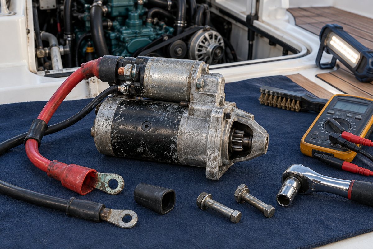
Understand What the Starter Circuit Does
On a typical gasoline or diesel inboard, sterndrive, or outboard, a start command energizes a relay or solenoid. The solenoid moves the starter drive into engagement and closes heavy contacts that feed battery current to the starter motor. The motor then turns the engine until it starts and the key or start control is released.
The exact arrangement varies. Some engines use a starter-mounted solenoid, an additional slave relay, an isolated ground terminal, a neutral-safety or gear-position circuit, an emergency-stop input, or electronic engine controls. An outboard may package the components under the cowl, while an inboard starter may sit low beside the flywheel housing where water, oil, and salt residue collect.
Use the engine wiring diagram and parts catalog. Never assume that a stud is a ground, a small terminal is the start input, or a replacement automotive starter is suitable for a marine gasoline-engine space.
Record the Symptoms Before Disconnecting Anything
If the engine currently starts, note how it behaves when cold and warm. Useful clues include:
- Normal, even cranking speed.
- Slow cranking that worsens after storage or in cool weather.
- A single click with no rotation.
- Rapid clicking.
- No click and no crank.
- Starter operation that continues after the control is released.
- Grinding, clashing, whirring, or delayed disengagement.
- Smoke, hot-cable odor, or a terminal that becomes warm.
Do not repeat a failing start attempt until the cables or starter overheat. Repeated cranking can damage the starter, solenoid, wiring, and battery. Follow the engine manual's maximum cranking time and required cooling interval.
Record engine hours, battery-bank selection, ambient temperature, and any relevant fault messages. A precise symptom is far more valuable to a technician than “starter bad.”
Isolate Energy and Prevent Accidental Starting
Before inspecting starter terminals or mounting hardware:
- Shut down shore-powered charging and onboard generation as applicable.
- Turn off the start battery switch or isolate the start battery according to the boat's procedure.
- Disable automatic or remote start functions.
- Remove the key or secure the start control.
- Confirm that the starter's main battery terminal is de-energized with a suitable meter.
Follow the engine maker's battery-disconnection sequence, especially on electronically controlled engines or multi-bank installations. A selector switch marked “Off” is not proof that every starter cable is dead. Charging sources, emergency parallel circuits, or wiring installed directly to a battery may remain energized.
Delco Remy starter instructions warn to disconnect the battery ground before removing or replacing starter cables. The safest detailed sequence is the one specified for your boat and engine.
Gasoline-engine spaces add another constraint: starters and other electrical components may need ignition protection. Preserve the approved equipment and configuration. A non-marine replacement or unauthorized repair to a sealed unit can introduce an ignition source where gasoline vapor may collect.
Inspect the Starter and Solenoid in Place
Use a bright light and mirror or inspection camera if access is limited. Do not lean on fuel rails, hoses, throttle linkages, or wiring harnesses to reach the starter.
Check for:
- Water tracks, bilge splash, salt crystals, oil, coolant, or fuel contamination.
- Rust swelling, cracked housings, loose end frames, or damaged protective coatings.
- Burned insulation, melted boots, soot, or discoloration at the solenoid.
- A loose starter body, missing bolt, cracked bracket, or damaged mounting flange.
- Evidence that a cable terminal can touch the engine block or another stud.
- Chafe or strain on the heavy positive cable and smaller control wires.
- An unsupported cable pulling sideways on a solenoid stud.
- A drain opening blocked by paint, sealant, debris, or an incorrect installation angle.
Do not wash the starter with a pressure washer or soak it with degreaser. Clean only as permitted by the engine or starter maker. Correct the source of water, coolant, or oil; replacing a contaminated starter without fixing the leak invites a repeat failure.
Starter mounting is not cosmetic. The mounting flange establishes alignment with the flywheel or ring gear and provides a reaction path for starter torque. If bolts are loose, the flange is damaged, or there is evidence of movement, stop and follow the model-specific installation procedure. Do not invent shims or torque values.
Inspect Cables, Terminals, and Boots
The starting circuit carries high current, so a small amount of resistance can cause a significant voltage loss and heat. Inspect the complete path from start battery positive to the starter and from the starter or engine ground back to battery negative.
Look for:
- Loose or rotated lugs.
- Green corrosion creeping under the insulation.
- Swollen cable, cracked jacket, exposed strands, or heat damage.
- Poorly crimped lugs, stacked terminals that do not sit flat, or incorrect hardware.
- Missing terminal boots and damaged insulating barriers.
- Cable routed across sharp edges or hot exhaust components.
- Corrosion between an engine ground lug and its mating surface.
- A battery switch, fuse, relay, or connector showing heat or corrosion.
Do not tighten a solenoid stud by twisting the outer nut without supporting the inner hardware as the manufacturer directs. The stud can rotate internally and damage the solenoid connection. Use the correct torque from the engine or starter manual. Generic values—even from the same starter brand—may not apply to your model.
If a lug is heavily pitted, strands are blackened, or corrosion has migrated under the jacket, replacement is usually more reliable than cosmetic cleaning. Use marine-grade cable of the specified gauge, insulation rating, and length, with properly crimped and sealed terminals. Keep boots and barriers in place after service.
Begin Diagnosis With the Battery
Starter diagnosis begins with a battery that is charged, visually sound, and able to pass the appropriate test. A resting voltage reading alone does not prove capacity. Follow the battery manufacturer's charging and test instructions, and evaluate every battery used in the start circuit.
Check battery terminals, interconnects, switches, and the negative return before blaming the starter. Rapid clicking often indicates that voltage collapses as the solenoid pulls in, although the exact cause still requires testing. A single click can result from inadequate current delivery, solenoid contact problems, a failed motor, or a mechanically locked engine. No click may point toward the control circuit, safety interlock, start relay, electronic control, or loss of power.
Never bridge solenoid terminals with a screwdriver. That shortcut can create an arc, bypass safety interlocks, crank the engine unexpectedly, or ignite vapor.
Use Voltage-Drop Testing Under Load
Resistance faults are best found while current is flowing. Delco Remy describes voltage-drop testing as the reliable way to determine whether the starting circuit provides an adequate current path and advises checking the battery before evaluating main starter cables.
The general principle is to measure the difference between the two ends of a conductor or connection while the starter is cranking:
- For the positive side, measure from the battery positive post to the starter's main battery terminal.
- For the negative side, measure from the starter ground point or case—as specified—to the battery negative post.
The meter reading represents voltage lost in that path. Test individual sections to locate the resistance: cable, battery switch, connection, solenoid contact, or ground bond. Make meter contact with the actual post or terminal identified by the procedure, not merely a clamp or bolt nearby.
Use the engine or starter manufacturer's limits. Delco Remy publishes limits for its heavy-duty products, but those figures should not be imposed on an unrelated marine starter. Cable length, system voltage, starter design, and test method matter.
This is a live high-current test. Keep loose clothing, leads, and tools clear of belts and pulleys; ventilate the space; follow gasoline-vapor precautions; and have a second person available when the engine maker calls for one. If you do not have the rated equipment or safe access, have a marine electrician or engine technician perform the test.
Interpret Cranking Clues Without Guessing
Use a sequence:
- Confirm the engine can be cranked safely and is not mechanically locked.
- Verify battery state and capacity.
- Inspect and test the main positive and negative current paths.
- Check the start-control circuit using the correct wiring diagram.
- Evaluate the starter and solenoid only after the supply and control paths are proven.
Delco Remy's diagnostic guidance separates complaints into slow crank, click/no-crank, and no-click/no-crank categories. That approach is useful because the same replacement part does not solve every symptom. For example, a no-click condition often points away from the motor and toward the solenoid control path, while a slow crank after batteries and cables pass their tests may justify starter evaluation.
Grinding or clashing calls for immediate attention. Possible causes include loose mounting, damaged pinion or ring-gear teeth, incorrect starter application, or engagement problems. Repeatedly trying the key can multiply the damage. A starter that stays engaged after release also demands prompt isolation; the fault may involve the control circuit, relay, solenoid, or drive mechanism.
Removal and Bench Service Are Not Routine Visual Maintenance
Starter removal can require supporting nearby components, protecting fuel and electrical systems, preserving shims, and accessing tight fasteners. Internal service may disturb ignition-protected construction. Do not remove or open the starter merely to “see if it looks good.”
If removal is justified, label and photograph every wire, isolate all sources, protect the exposed cable ends, and follow the engine manual. Keep mounting bolts, shims, brackets, and terminal hardware identified. Have a marine-qualified shop test or rebuild the correct unit when required.
Choose a replacement by engine serial number and approved application, not just housing size or tooth count. Match voltage, rotation, pinion, mounting, terminal orientation, grounding scheme, and ignition-protection requirements. Confirm that cables clear the block and cannot contact grounded metal. Delco Remy installation instructions specifically warn that a terminal must not touch engine metal after installation.
Prepare the Starter System for Storage
Once inspection and any repairs are complete:
- Make sure terminal boots and protective covers are secure.
- Support cables so they do not load the solenoid studs.
- Correct bilge water, spray, oil, or coolant sources.
- Leave intentional starter drains unobstructed.
- Confirm mounting hardware is secure to the correct specification.
- Preserve the battery according to its chemistry and the engine maker's storage procedure.
- Do not leave a known intermittent start fault for spring.
If the boat stays in the water or must remain ready for emergencies, maintain the starting system in operational condition. Storage steps must not compromise bilge pumping, alarms, or other required loads.
Spring Recommissioning
Before the first start, inspect the starter area again for corrosion, animal damage, leaks, and loose cables. Restore batteries and switches in the specified sequence. Confirm the engine compartment is safe and ventilated, then make the first start while watching the voltmeter and listening to the crank.
The starter should engage promptly, crank evenly, disengage cleanly, and produce no grinding or repeated clicking. After shutdown and isolation, check for unexpected heat or movement at serviced connections. A warm high-current connection can indicate resistance even when the engine started.
Marine Starter Inspection Checklist
- Record engine hours and the exact cranking symptom, if any.
- Identify engine, starter, solenoid, system voltage, and wiring diagram.
- Disable remote or automatic starting and isolate every power source.
- Inspect for water, salt, oil, coolant, heat, and housing damage.
- Check starter mounting, flange, bolts, brackets, and alignment clues.
- Inspect positive cable, negative return, control wires, boots, and supports.
- Correct corroded, loose, overheated, chafed, or strained connections.
- Test the start battery before condemning the starter.
- Perform voltage-drop tests only with the correct procedure and safe equipment.
- Investigate clicks, grinding, delayed disengagement, or hot connections.
- Use only an approved marine replacement for the exact engine application.
- Recheck the system during spring recommissioning.
Keep a Useful Maintenance Record
In BoatDuty, record engine hours, starter part number, battery configuration, cable size if known, symptom category, battery-test result, cranking voltage, positive- and negative-side voltage drop, connection repairs, torque references, and the date of the next check. Note whether a technician recommended starter removal, ring-gear inspection, or control-circuit diagnosis.
That history helps distinguish a new problem from a recurring one. It also prevents the common cycle of replacing a starter before confirming the battery, cables, switches, grounds, and control circuit that feed it.