

Marine engine mount inspection is easy to overlook because the mounts sit low in the engine compartment and rarely demand attention until vibration, alignment, or structural problems become obvious. A careful inspection before winter storage can reveal deteriorated rubber, loose hardware, corrosion, damaged engine beds, and early clues that the drivetrain needs professional alignment work.
This guide focuses on flexible mounts used with inboard engines and many marine generators. It does not provide universal torque values, mount heights, or coupling tolerances. Those details depend on the engine, transmission, coupling, shaft arrangement, hull, and mount design. Follow the boat builder’s documentation and the engine, transmission, and mount manufacturers’ instructions for your exact installation.
Why Marine Engine Mounts Deserve an Annual Inspection
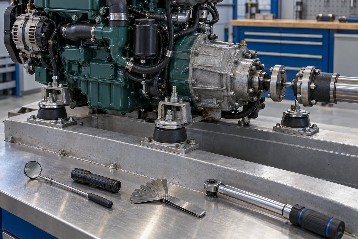
Engine mounts do more than hold the machinery in place. They support the engine and marine gear at the designed height and angle, isolate some vibration from the hull, and help preserve alignment between the transmission coupling and the propeller shaft on a conventional inboard system.
YANMAR’s current Marine Installation Manual treats engine mounting and shaft alignment as an integrated installation task, while its repower guide emphasizes using mounts specified for the engine model. The guide notes that the correct mounts are designed to reduce the transfer of engine noise and vibration to the hull. That is why an apparently similar automotive or generic industrial isolator is not automatically a suitable substitute.
Mount problems can develop gradually. Rubber ages, petroleum products soften some elastomers, fasteners corrode, locknuts move, and the engine bed beneath a mount can deteriorate. A pre-storage inspection creates time to investigate without delaying the first launch of spring.
Confirm What Type of Installation You Have
Before inspecting anything, identify the propulsion arrangement.
- Straight-shaft and V-drive inboards: Mount condition and engine-to-shaft alignment are closely related.
- Sterndrives: The engine mounts and transom assembly are part of a different alignment system. Use the drive manufacturer’s specified alignment procedure and tools.
- Saildrives: Mounting geometry, flexible diaphragms, and service limits are model-specific.
- Pod drives and integrated propulsion systems: Inspection and alignment should follow the propulsion manufacturer’s service documentation.
- Marine generators: Flexible mounts support the generator set, but there is no propeller-shaft coupling to align. Check the generator manufacturer’s mount and exhaust-clearance instructions.
Record the engine or generator model, mount part number if visible, and the installed arrangement before ordering parts. Even within one engine family, front and rear mounts may have different load ratings.
Make the Engine Compartment Safe
Inspect only with the engine fully stopped and cool.
- Remove the ignition key or disable the starting circuit according to the owner’s manual.
- Turn off remote-start capability on a generator.
- Secure the battery switch or starting system so another person cannot crank the engine.
- Ventilate the compartment and clean up fuel, oil, or coolant before working near the mounts.
- Use stable lighting rather than reaching around belts, couplings, or hot exhaust components.
Do not run the engine with guards removed or place tools near a rotating coupling. If operational observation is needed, leave it to a qualified technician using the prescribed safety procedure.
Inspect the Rubber Isolators Carefully
Use a bright light and an inspection mirror to view every side of each flexible mount. Look for:
- Cracks, splits, missing pieces, or a glazed surface
- Rubber separating from the bonded metal plate
- Bulging, flattening, or visibly uneven compression
- A mount that sits noticeably lower than the others
- Metal-to-metal contact that defeats vibration isolation
- Oil, diesel fuel, coolant, or cleaning chemicals soaking the rubber
- Rust trails, fretting dust, or shiny movement marks around the mount
A small surface mark is not automatically a failed mount, and different mount designs compress differently. Compare like positions, photograph anything questionable, and consult the mount manufacturer’s criteria. Do not pry on the rubber or lift the engine with a jack unless the service procedure specifically calls for it and the engine is properly supported.
Fluid contamination deserves prompt attention. Replacing a softened isolator without repairing the oil, fuel, or coolant leak that damaged it only resets the clock on the same failure.
Check Brackets, Studs, Locknuts, and Bed Fasteners
Trace the complete load path from the engine bracket to the hull structure. Inspect:
- Engine-side mounting brackets for cracks, bending, and corrosion
- Threaded adjustment studs for damaged threads or unusual lean
- Upper and lower adjustment nuts and locknuts for visible movement
- Mount baseplates for distortion or corrosion
- Bolts, lag screws, washers, and backing plates securing the mount to the bed
- Witness marks showing a baseplate has shifted
Do not apply a generic torque value. Mount hardware may thread into a steel bed, an aluminum bracket, an embedded plate, or a tapped component, and the required torque can vary with fastener grade, diameter, thread condition, and manufacturer. If a fastener is loose, determine why it loosened and obtain the correct specification before tightening it.
Avoid turning an adjustment nut simply to make it look even with another mount. Those nuts establish engine position and coupling alignment. A small height change at one mount can alter the drivetrain geometry.
Examine the Engine Beds and Surrounding Structure
A sound mount cannot compensate for a damaged foundation. Clean enough of the area to inspect the engine beds or stringers beneath all four corners.
On fiberglass boats, look for cracked tabbing, crushed laminate, separated reinforcement, moisture staining, or a washer sinking into the surface. On metal beds, check welds, brackets, fasteners, and coatings for corrosion or fatigue. On timber beds, watch for soft material, swollen grain, and fasteners that no longer hold securely.
Also check that hoses, exhaust components, wiring, and control cables have adequate clearance around the engine. A sagging mount can allow a hose to chafe, an exhaust connection to carry unintended load, or a moving component to contact the hull.
Structural damage, a loose embedded plate, or deteriorated stringer material is not a cosmetic repair. Have the foundation evaluated before the engine is realigned.
Look for Alignment Clues Without Disturbing the Coupling
An annual visual inspection can identify reasons to schedule an alignment check, but it cannot prove that alignment is correct. Potential warning signs include:
- New or increasing vibration at a particular engine speed
- A coupling that shows fretting debris, polished movement marks, or damaged fasteners
- Uneven wear or heat discoloration near the coupling
- Repeated shaft-seal leakage after the seal itself has been serviced
- A mount adjusted near the end of its usable thread range
- A visibly tilted adjustment stud or shifted baseplate
- Recent grounding, propeller impact, shaft work, engine removal, or structural repair
Do not insert a feeler gauge into the coupling or loosen coupling bolts merely for a casual check. Correct alignment work may require disconnecting the coupling, checking face and rim relationships, accounting for shaft support and hull condition, and tightening mount hardware in a controlled sequence. The permitted values and method come from the propulsion manufacturer’s installation manual.
Hull loading also matters. A boat supported ashore may not have exactly the same shape as it does afloat. Ask the boat builder or service yard whether final alignment for your installation must be checked in the water and after the hull has settled.
Decide Whether the Mount Needs Cleaning, Monitoring, or Replacement
Light surface dirt can usually be removed with a cloth and a cleaner approved by the mount or engine manufacturer. Avoid solvents, aggressive degreasers, and petroleum-based dressings unless the documentation specifically permits them. They may damage the elastomer or hide a leak.
Schedule professional service when you find separated rubber, severe compression, broken brackets, damaged threads, loose foundation hardware, structural deterioration, unexplained vibration, or evidence the engine has moved. Replacement mounts must match the engine’s load, position, and installation requirements. Replacing only one mount may be appropriate for some systems, while age or contamination may justify evaluating the full set.
Marine Engine Mount Inspection Checklist
- Identify the engine, transmission, propulsion type, and mount model where possible
- Disable starting and remote-start circuits
- Photograph all mount positions before cleaning or adjustment
- Check rubber for cracks, separation, bulging, and contamination
- Inspect brackets, studs, locknuts, and baseplates
- Examine mounting bolts, washers, backing, and engine beds
- Look for movement marks, corrosion, and fretting debris
- Verify clearance around hoses, wiring, controls, and exhaust components
- Note recent impacts, shaft work, engine removal, or vibration changes
- Obtain model-specific torque and alignment instructions before repair
- Arrange professional alignment or structural inspection when indicated
Record the Inspection in BoatDuty
An engine mount problem is much easier to evaluate when you can compare it with earlier observations. In BoatDuty, record the inspection date, engine hours, engine and transmission models, mount identification, visible condition, leaks found, and any vibration symptoms. Add notes about photographs, hardware checked, products used for cleaning, and repairs recommended or completed.
If a technician measures alignment or replaces mounts, keep the service date, parts used, applicable specifications, and follow-up recommendations with the maintenance record. That history helps distinguish a new change from an old stain or harmless casting mark the next time the engine compartment is inspected.