

A marine DC electrical panel inspection before storage can expose small problems while they are still visible: a loose branch-circuit terminal, green corrosion creeping under insulation, a breaker that no longer operates cleanly, or heat discoloration around a high-resistance connection. Correcting those clues now reduces the chance of an intermittent failure—or a dangerous hot spot—when the boat returns to service.
This article covers low-voltage DC distribution panels commonly used on 12- or 24-volt recreational boats. It does not cover shore-power AC panels, electric-propulsion battery packs, or high-voltage hybrid systems. Those require their own procedures and qualified service. Always follow the boatbuilder's wiring diagram and the panel, inverter/charger, battery, and battery-management-system manuals.
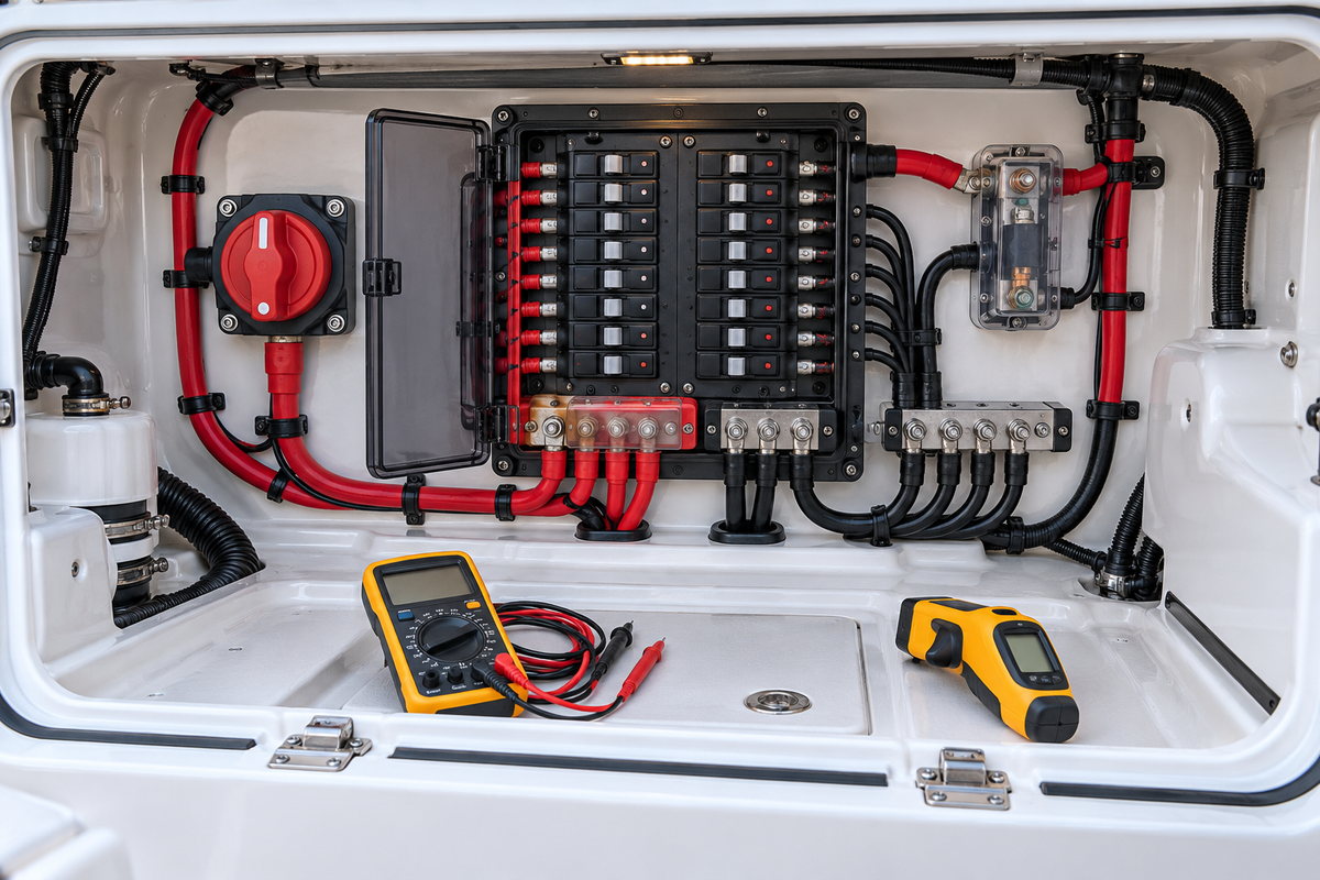
First, Make the DC Panel Safe to Inspect
Turning off the branch breakers is not enough. A panel's main feed, battery switch wiring, bilge-pump supply, memory circuits, solar controller, alternator, charger, inverter/charger, or automatic charging relay may leave parts energized. Some feeds intentionally bypass the main panel.
Before opening a panel:
- Secure the boat and switch off all loads normally controlled by the panel.
- Disconnect shore power and disable the generator, if fitted, so no charger can re-energize the battery bank.
- Shut down solar, wind, alternator, and inverter/charger sources according to their manufacturers' sequences.
- Follow the battery or battery-management-system shutdown procedure. Turn battery switches off and isolate the relevant negative and positive feeds in the order specified by the equipment manuals.
- Verify absence of voltage with a suitable meter at the exact conductors you will touch. Prove the meter on a known source before and after the test.
- Protect disconnected cable ends from accidental contact and prevent anyone from restoring power.
If you cannot identify every source, stop. Do not assume wire color or a switch label proves a conductor is dead. Blue Sea Systems' panel documentation is model-specific, and its instruction library includes separate manuals for DC distribution panels, combined AC/DC panels, battery-switch panels, and below-deck breaker panels. Use the part number on the actual panel.
Compartments containing gasoline vapor present an additional issue: not every breaker, switch, or panel is ignition protected. Do not operate or service non-ignition-protected equipment in a potentially explosive atmosphere. Ventilate as the boatbuilder requires and have qualified marine service resolve questionable installations.
Inspect the Front Before Removing Fasteners
Start with the panel closed. A good front-side inspection creates a baseline without disturbing wiring.
Look for:
- Missing, duplicate, vague, or handwritten labels that no longer match the connected load
- Breakers that sit at different angles, feel loose, or will not latch consistently
- Cracked toggle guards, broken actuator handles, loose mounting screws, or a warped faceplate
- Backlights or indicator lamps that were dim, intermittent, or unusually warm during the season
- Soot, melted plastic, amber or brown discoloration, blistered labels, or a burnt odor
- Moisture tracks, salt deposits, green staining, or corrosion around panel edges and fasteners
- Added holes, unsupported accessories, or improvised jumpers visible from the front
Operate each breaker only after the system is safely configured for the test. A breaker is protective equipment, not merely a switch; replace a damaged or unreliable device with a model of the correct type, voltage rating, interrupt rating, pole arrangement, and current rating specified for that circuit. Do not increase amperage to stop nuisance trips. Repeated tripping is a diagnostic clue, not permission to install a larger breaker.
Open the Panel Without Stressing the Harness
Photograph the front and rear before moving anything. Support the panel as it opens so its weight does not hang from the conductors. Many panels use hinges, service loops, or removable fasteners; follow the manufacturer's arrangement. If wires are too short to open the panel without strain, do not pull harder—have the harness corrected.
Keep metal tools controlled. Remove jewelry and avoid laying hardware where it can bridge terminals if an overlooked circuit remains energized. Even low-voltage battery systems can deliver extremely high fault current.
Read the Wiring as a System
A well-built DC panel is understandable at a glance. Positive feeders and branch conductors should land on the intended breakers or bus, negative returns should reach the proper negative bus, and cables should be supported so terminals do not carry mechanical load. Conductors should be protected from sharp edges and kept clear of heat, moving parts, water paths, and fuel-system components.
Compare the wiring with the current diagram. Check for:
- Ring terminals fully seated on studs, with no lug resting on insulation or at an angle
- Correct hardware order and enough thread engagement without stacked improvised washers
- Properly crimped marine terminals and intact strain-relief heat-shrink
- No bare strands, fork terminals where the device requires rings, household wire nuts, or solder-only repairs unsupported against vibration
- Branch conductors sized and protected for their load and length under the boatbuilder's design
- Feeder overcurrent protection located and rated as specified by the system design
- Separate, orderly positive and negative paths rather than unidentified cross-connections
- Secure cable clamps and a service loop that permits access without tension
- Covers over exposed positive buses and terminal studs
Victron Energy's Wiring Unlimited emphasizes that poor connections introduce resistance, which causes voltage drop and localized heating. Its guidance also stresses correct cable sizing, fusing, connections, and system drawings. The lesson applies beyond one brand: a connection can look intact while generating heat under load.
Find Corrosion Before It Travels
Green or blue deposits on copper, white powder on plated parts, blackened strands, and rust on steel hardware are all reasons to investigate. Corrosion may start at a loose crimp, an unsealed wire end, a leaking deck fitting above the panel, condensation, or a wet cable run. It can travel under insulation beyond the visible deposit.
Do not simply spray the entire panel. First identify and stop the moisture source. With the circuit de-energized, disconnect only one labeled conductor at a time when the manual permits, and photograph its position. Replace damaged terminals and cut back to clean, bright conductor only if enough cable remains for a properly supported connection. If dark or stiff strands continue under the insulation, replace the affected cable run rather than hiding the damage under a new terminal.
Use only cleaners and corrosion-protection products approved by the equipment manufacturer. Residue from an unsuitable product can attract dirt, attack plastics, or interfere with electrical contact. Never coat a contact surface unless the component maker specifies it.
Treat Heat Clues as Evidence, Not Cosmetics
Heat discoloration, softened insulation, a distorted breaker case, or a scorched lug indicates abnormal resistance, overload, poor contact, or an incorrectly selected device. Replacing a melted boot without finding the cause leaves the fault in place.
Investigate the complete current path: source connection, feeder, main protection, bus, breaker, branch terminal, load, and return. Confirm the connected load and breaker rating against the approved diagram. Verify terminal compatibility and the manufacturer's torque specification. Do not “tighten everything” by feel; small studs and breaker screws can be damaged by excess torque, while an under-torqued connection remains resistive. If a fastener has been overheated, the breaker or bus may have lost spring pressure or plating and may require replacement.
A thermal image or infrared thermometer is useful only on an energized system under a known, stable load—and that test introduces risk. A qualified marine electrician can compare similar circuits and inspect for abnormal temperature rise while maintaining covers and safe clearances. Surface temperature varies with emissivity, airflow, load, and viewing angle, so an isolated number without context is not a diagnosis.
Test Voltage Drop Under Load
Continuity checks on a dead circuit can miss a high-resistance connection. Voltage-drop testing measures the loss across a connection or cable while current is flowing. It is often the better method for diagnosing dim lights, slow motors, electronics resets, or a warm terminal.
The exact procedure depends on the circuit. The system must be energized and loaded, so only perform the test if you are competent to work safely around the installed battery system. Place meter leads across the section being evaluated and compare the reading with the equipment manual or service specification. Test both positive and negative paths. Do not use a generic voltage-drop limit when the manufacturer publishes a circuit-specific value.
Record battery voltage, load state, current when available, test points, and measured drop. That evidence helps separate a panel connection problem from a weak battery, undersized cable, failing motor, or poor ground farther downstream.
Breakers, Buses, and Labels Deserve Separate Checks
Branch breakers
Inspect the case, terminals, actuator, mounting, and rating. A breaker that trips repeatedly, will not reset, feels gritty, or shows heat damage should be diagnosed and replaced with an approved equivalent. Never bypass it with foil, a jumper, or a higher-rated device.
Main feed and positive bus
This path carries the combined panel load. Examine protective boots and covers, feeder lugs, bus plating, signs of arcing, and the upstream fuse or breaker. Check that added circuits were not stacked onto a stud beyond the device maker's allowance.
Negative bus
A loose return can mimic a positive-side fault and create erratic electronics behavior. Inspect every terminal for corrosion, heat, crowding, and strain. Confirm that high-current or sensitive circuits follow the builder's intended return paths.
Panel backlighting and labels
Small lighting conductors can become a tangle of unsupported splices. Trace them, inspect their protection, and replace illegible labels. A clear label should identify the actual load and, where useful, its location. Update the wiring diagram at the same time.
Recommission Methodically
Before closing the panel, remove loose hardware and tools, confirm that every disconnected conductor is restored, fit terminal covers, and check that no cable will be pinched. Reinstall the panel with its service loop supported.
Restore charging sources and batteries in the sequence specified by their manufacturers. Energize the main feed, then branch circuits one at a time. Check for unexpected current draw, odor, noise, heat, or a breaker that trips. Test critical circuits—including bilge pumps, navigation lights, communications equipment, and alarms—using their own procedures. A final under-load check is the time to verify the repair, not the first time to discover a misplaced conductor.
Marine DC Panel Inspection Checklist
- Locate the current boat and panel wiring diagrams
- Identify every battery, charging, inverter, solar, and bypass feed
- Isolate sources and verify absence of voltage before opening the panel
- Photograph the front and rear before disturbing wiring
- Check breaker operation, ratings, labels, and heat damage
- Inspect feeder, positive bus, negative bus, lugs, crimps, and covers
- Trace corrosion to its moisture source
- Check cable support, chafe protection, service loops, and strain relief
- Use manufacturer torque values rather than tightening by feel
- Diagnose nuisance trips instead of increasing breaker size
- Perform energized voltage-drop or thermal tests only with appropriate skill and controls
- Recommission one circuit at a time and test critical loads
Make the Panel Inspection Repeatable
Use BoatDuty to record the inspection date, battery-bank voltage, engine hours if relevant to the charging system, breaker and panel part numbers, terminal repairs, cable sizes, torque specifications, measured voltage drops, products used, and photos before and after service. Note any deferred repair and the circuit left disabled. At the next inspection, those records reveal whether discoloration, corrosion, or an intermittent load has returned.
A clean-looking panel is not necessarily a healthy one. The safest inspection follows the energy sources, the current path, and the equipment manuals. Done carefully, it turns vague electrical symptoms into specific, traceable maintenance actions before storage hides the clues.