

Carbon monoxide is colorless, odorless, and potentially fatal. On a boat, it can come from gasoline or diesel engines, generators, cooking appliances, heaters, or another vessel operating nearby. A working marine carbon monoxide alarm is therefore not a fit-and-forget accessory. It is a life-safety device that needs a visible power indication, a successful test, a suitable location, and replacement before the sensor reaches the end of its rated life.
An end-of-season inspection is a practical time to document every alarm aboard, correct power or mounting problems, and order replacements before spring. The exact test sequence, indicator pattern, installation location, and service life are model-specific, so identify the alarm first and keep its manual with the boat’s maintenance records.
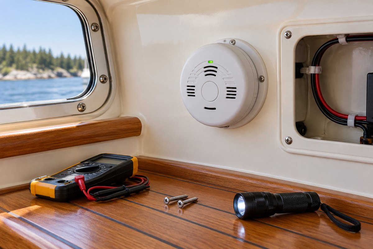
Understand What the Alarm Can—and Cannot—Do
A carbon monoxide alarm monitors the air in an accommodation space and sounds when its programmed exposure threshold is reached. It does not replace maintenance of engines, generators, fuel-burning appliances, ventilation, or wet-exhaust components. It also is not automatically a smoke, propane, or gasoline-vapor detector unless the product is specifically listed and labeled for those additional functions.
The U.S. Coast Guard advises boaters to install and maintain CO alarms inside the boat, never ignore an alarm, and replace alarms as directed by their manufacturers. Its trip checklist also calls for testing each CO detector with its test button before getting underway. Treat the alarm as one layer in a wider prevention system that includes sound exhaust equipment, adequate ventilation, and awareness of exhaust from nearby boats.
Never test a CO alarm with engine exhaust, a generator, a flame, or a chemical spray. Use the manufacturer’s test control and procedure. Deliberately introducing combustion gas can expose people to CO and still may not prove that the installation is correct.
Start With an Alarm Inventory
Before removing a panel or pressing a button, make a short inventory. For each alarm, record:
- Manufacturer and model number
- Battery-powered or boat-powered configuration
- Location aboard
- Manufacturing, activation, installation, and replace-by dates, if shown
- Normal indicator pattern described in the manual
- Meaning of alarm, fault, low-power, and end-of-life signals
- Test interval and exact test-button sequence
- Replacement part number or current approved successor
Do not assume that all alarms on the same boat behave alike. A current Fireboy-Xintex CMD6 model, for example, has an approximate seven-year end-of-life period, but that figure must not be applied to another make or model. The permanent battery in some sealed alarms is not a user-serviceable substitute for replacing the complete unit at end of life.
Confirm Location and Keep the Sensor Unobstructed
Inspect each alarm in place before taking it down. It should be where the alarm manufacturer and the boatbuilder intended—not hidden behind a curtain, cushion, stored jacket, or newly installed cabinet door. Check that a hatch, portlight, air-conditioning outlet, heater outlet, or cooking appliance has not changed the airflow around it.
Fireboy-Xintex guidance for its marine alarms calls for coverage of the main cabin and each sleeping area, with placement details and separation from dead-air spaces, cooking appliances, vents, and sources of moisture. Those dimensions and rules are model-specific. Use the instructions for the alarm actually installed rather than moving it according to a generic online diagram.
The sensing openings must remain clear. Look for dust, paint, tape, polish residue, insect debris, or evidence that cleaning spray reached the housing. Do not poke a tool or compressed-air nozzle into the openings. Do not paint the case. If the manual permits surface cleaning, follow its method; otherwise, use only a dry, soft approach around the exterior and contact the manufacturer if contamination is suspected.
Inspect the Housing, Mount, and Labels
With the boat secured and the relevant electrical circuit isolated when required, inspect the physical installation:
- Confirm that the housing is not cracked, warped, heat-discolored, or loose.
- Check that the alarm locks fully onto its mounting base.
- Inspect mounting screws and the surrounding bulkhead for looseness or water staining.
- Make sure the test/mute control moves normally and is not jammed.
- Verify that model, date, warning, and indicator labels remain readable.
- Look nearby for leaks, condensation, or signs that spray reaches the alarm.
A cracked or contaminated alarm is not a repair project. Fireboy-Xintex states that its alarms are not field-serviceable. When a life-safety device has physical damage, an unresolved fault indication, or a failed test, follow the manual and manufacturer support guidance; replacement is commonly the correct outcome.
Check Power Without Creating a New Fault
Battery-only, permanently sealed, boat-powered, and interconnected alarms require different checks. Do not pry open a sealed unit or substitute a battery chemistry that the manual does not authorize.
For a boat-powered alarm, first observe the normal power indicator. If it is absent or abnormal, isolate the branch circuit before touching wiring. Then inspect only accessible, approved service points for a loose connector, corrosion, chafe, an incorrect fuse, or a tripped breaker. Restore power and test voltage only if you are equipped to do so safely and have the wiring diagram. Measure at the alarm supply under the conditions specified by its manufacturer; a healthy battery reading elsewhere does not rule out voltage drop at the device.
If alarms are interconnected or tied to a generator-shutdown relay, use the manufacturer’s complete test procedure. A local horn test does not automatically prove that every interconnected alarm, remote annunciator, or shutdown interface works.
Perform the Manufacturer’s Test Sequence
Test with the boat in a quiet condition so the horn and indicators can be observed. Warn anyone aboard before starting. Press and hold the test control exactly as the manual describes, then confirm the required light pattern and audible sequence.
Test intervals vary. The Coast Guard recommends pressing each detector’s test button before a trip. A legacy Fireboy-Xintex CMD5 manual calls for testing at least weekly and after the alarm has been unused for ten days or more. Those instructions demonstrate why the correct model manual matters; do not turn one product’s interval into a universal rule.
During the test, verify all of the following that apply:
- Normal power indication exists before the test.
- The horn is clear and loud, not weak or intermittent.
- Indicator colors and flash patterns match the manual.
- Interconnected alarms respond as specified.
- A connected relay or shutdown function completes its separate approved test.
- The unit returns to its documented normal state afterward.
If the alarm fails, do not silence the problem by disconnecting it and leaving the berth unprotected. Check the manual’s troubleshooting steps, correct a verified supply fault if appropriate, and replace or obtain qualified service for the device before anyone sleeps aboard or operates combustion equipment.
Recognize End-of-Life and Fault Signals
Low power, sensor fault, alarm, and end-of-life indications are not interchangeable. Write the patterns from the manual into the maintenance record so a future owner or crew member does not have to guess at a chirp in the middle of the night.
Check the manufacturing or activation date even when the unit passes its button test. The test control can confirm the alarm’s programmed self-test response, but it does not extend the sensor’s rated life. Replace the alarm at the manufacturer’s stated interval and whenever its end-of-life signal appears. If the date is unreadable and age cannot be documented, ask the manufacturer how to identify the unit; do not assume that a quiet alarm is a current alarm.
When replacing a unit, match its intended marine application, power arrangement, voltage, mounting requirements, and any interconnect or relay functions. A household alarm is not automatically a suitable direct replacement for a marine model. De-energize the circuit, follow the wiring instructions, and use a qualified marine technician when the work involves concealed wiring, generator shutdown, or a change of system design.
Pair Alarm Maintenance With an Exhaust Check
An alarm inspection should prompt a look at the sources it guards against. Before storage and again at commissioning, examine accessible exhaust hoses, clamps, fittings, and generator or heater exhaust components for water tracks, soot, rust streaks, looseness, scorching, cracking, or an altered exhaust sound. Confirm cooling-water discharge when starting engines or a generator as the applicable manual requires.
Do not run an engine or generator in an enclosed shed merely to complete a checklist. Make functional checks only where ventilation and operating conditions are safe. Exhaust defects, recurring CO alarms, or unexplained symptoms call for a qualified marine technician, not repeated resets.
End-of-Season CO Alarm Checklist
- Inventory every CO alarm and record its exact model.
- Find the manual and decode all indicator and chirp patterns.
- Confirm that each accommodation and sleeping area is protected as required.
- Remove nearby obstructions without relocating the alarm casually.
- Inspect the housing, vents, mount, labels, and surrounding area.
- Verify the normal power indication.
- Inspect accessible supply wiring only with the circuit safely isolated.
- Run the model-specific test and confirm horn, lights, and interconnection.
- Check manufacturing, activation, and replacement dates.
- Replace expired, damaged, contaminated, faulted, or failed units as directed.
- Inspect related exhaust and ventilation items within your maintenance scope.
- Retest after service and again before the boat returns to use.
Record the Result in BoatDuty
A useful BoatDuty entry should capture the test date, alarm location, manufacturer, model, power type, manufacturing or activation date, replacement deadline, observed indicator sequence, and test result. Note any wiring repair or replacement part number, and attach the exact manual reference to your records if available. For a boat with several alarms, create a clear entry for each location rather than recording only “CO alarms checked.”
That history turns an easy-to-forget safety device into a scheduled maintenance item. It also makes spring commissioning faster: you can see which alarm was replaced, which one is approaching end of life, and whether an abnormal chirp has appeared before.
When to Stop and Call a Professional
Arrange qualified service when an alarm repeatedly faults, a boat-powered unit has abnormal voltage, interconnected devices do not communicate, a generator-shutdown interface fails, wiring is heat-damaged or corroded inside a concealed space, or an alarm activates without an immediately obvious and safely corrected cause. If a CO alarm sounds, treat it as a real hazard: move people to fresh air, contact emergency services, ventilate only from a safe position, and do not re-enter or restart equipment until the source has been found and corrected.