

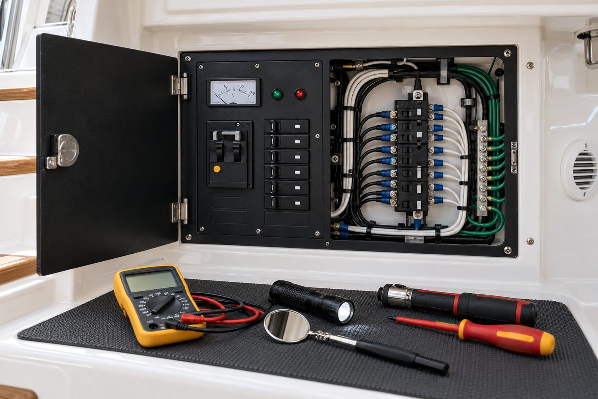
A marine AC electrical panel distributes shore, generator, or inverter power to the boat’s 120- or 240-volt loads. It also concentrates many of the devices that protect people and wiring: main and branch circuit breakers, source selectors, reverse-polarity indicators, leakage protection, meters, neutral buses, and safety-ground connections. End-of-season layup is a useful time to inspect this equipment because recurring heat, moisture, looseness, or nuisance trips can be documented before months of storage make the evidence harder to interpret.
This is not a live-electrical-work project. An apparently dark panel may still be energized by shore power, a generator, an inverter, an inverter/charger in transfer mode, or a second inlet. Owners can perform a careful external inspection and operate user-accessible test controls as the manuals direct. Removing covers, checking terminal torque, measuring insulation resistance, or diagnosing source-transfer and grounding faults should be assigned to a qualified marine electrician unless the owner is trained and equipped for that work.
Identify Every AC Source Before Touching the Panel
Start by drawing a simple source map. Record every device that can energize the panel:
- each shore-power inlet;
- the generator;
- a standalone inverter;
- an inverter/charger with an internal transfer relay;
- an isolation transformer; and
- any secondary AC panel or subpanel.
Do not assume that switching off the main breaker removes power from the conductors on its source side. The line terminals, source selector, transfer equipment, or inverter output may remain energized. Follow the boatbuilder and equipment manuals to disconnect shore power, stop the generator, disable automatic generator start, switch off the inverter, and isolate its DC supply where required. Secure the controls against an unexpected restart.
If the panel has more than one source, verify that the selector or interlock prevents incompatible sources from being connected together. Do not force a stiff selector or defeat a lockout slide. A source selector that binds, feels vague, or permits an unintended combination needs professional correction.
Record the Panel and Protection Devices
Photograph the closed panel before moving any breaker. Record the panel manufacturer and model, nominal voltage, main-breaker rating, source-selector arrangement, ELCI or residual-current device model, meter type, and branch-circuit labels. Note whether the installation uses:
- a conventional double-pole main breaker;
- an equipment leakage circuit interrupter, commonly called an ELCI;
- branch GFCI or residual-current protection;
- reverse-polarity lamps or alarms;
- separate shore, generator, and inverter sections; or
- a combined AC/DC panel.
Not every boat has every device. Blue Sea Systems’ current ELCI main panels combine overcurrent and leakage protection and include a reverse-polarity indicator, but the leakage rating and test procedure belong to the exact installed product. Do not use a neighboring panel’s specifications or substitute a household breaker because the toggle looks similar.
Inspect the Panel Face With All Sources Off
With the system safely de-energized, clean the panel face using the method approved by its manufacturer. Avoid spraying cleaner through breaker openings, meter vents, test buttons, or indicator lenses. Inspect for:
- brown or black discoloration around a breaker;
- a warped faceplate, melted label, or blistered finish;
- a breaker handle that sits between positions;
- a cracked toggle, loose bezel, or missing fastener;
- condensation, water tracks, mineral residue, or green corrosion;
- a cloudy meter lens or moisture behind it;
- a failed backlight or loose circuit label;
- an ELCI or GFCI that will not reset; and
- improvised labels that no longer match the actual load.
Heat discoloration deserves immediate attention even if the circuit still works. Circuit breakers are not precision current limiters at the number printed on the handle. Blue Sea Systems notes that wires and protective devices can heat significantly near their rated load and that many thermal breakers do not trip until current is above the nominal rating for a period of time. A high-resistance terminal can create additional localized heat without producing a clean overload trip.
Do not repeatedly reset a breaker that trips. Record which loads were operating, whether the trip occurred immediately or after time, and whether the breaker face or surrounding panel was warm. A trip can indicate overload, leakage, a damaged appliance, a weak breaker, or a wiring fault. Resetting without diagnosis can erase the most useful symptom.
Check Breaker Operation Without Forcing It
With power still isolated, move each user-operable breaker fully OFF and then ON only if the manufacturer permits exercising it during maintenance. The action should be positive and consistent. A handle that is loose, gritty, unusually stiff, or unable to latch belongs on the repair list.
Return breakers to the storage positions specified by the boatbuilder. Some owners prefer every branch OFF during layup; others need a documented circuit energized for a heater, charger, or monitoring system. The correct answer depends on the boat’s storage plan. Never leave an unidentified circuit on.
If a breaker has a trip-free mechanism, holding the handle ON should not prevent an internal trip. Do not try to prove that characteristic with improvised loading. Breaker calibration, interrupting capacity, polarity, pole count, and ignition-protection requirements are replacement specifications, not visual preferences.
Treat Reverse Polarity as a Stop Signal
The reverse-polarity indicator is not a decorative lamp. Blue Sea Systems advises immediately disconnecting shore power when a reverse-polarity indication appears because the condition may involve reversed hot and neutral conductors, a floating neutral, or a missing safety ground. Do not silence the lamp, swap conductors aboard the boat to accommodate one pedestal, or continue using power because appliances seem normal.
A faint reverse-polarity glow can have causes different from a bright warning, including small leakage paths in the sensing circuit. Even so, diagnose it with the panel and boat documentation rather than dismissing it. Record when the indication occurs, which source is selected, and whether it follows the boat to another known-good supply. Let a qualified technician determine whether the fault is on the boat, at the pedestal, or in connected equipment.
Test ELCI and GFCI Devices Only as Directed
An ELCI monitors the boat’s AC supply for leakage imbalance; a GFCI or similar device commonly protects a branch circuit or receptacle location. Use each TEST and RESET control at the interval and under the conditions stated by its manufacturer. Some procedures require the circuit to be energized. If so, close the panel and restore one verified source exactly as the manual directs before testing.
Pressing a device’s test button checks that device’s internal mechanism and sensing path. It does not certify the entire boat’s grounding, bonding, neutral switching, or downstream wiring. Victron’s electrical-safety guidance specifically cautions that an RCD test button is not a test of the whole installation. An inverter or inverter/charger can change the required neutral-to-ground arrangement when it transfers between external power and inverter power, so failures that appear only on one source need system-level diagnosis.
If an ELCI or GFCI will not trip, will not reset, trips again immediately, or behaves differently on shore, generator, and inverter power, take the affected circuit out of service. Do not bypass it or install a higher trip threshold.
Inspect Behind the Panel Only When Qualified
Opening a panel exposes terminals that can be lethal and may remain energized upstream even when all visible breakers are off. A qualified person should verify absence of voltage with a properly rated tester and follow the panel manufacturer’s procedure before removing barriers.
With the system proven de-energized, the inspection should look for:
- loose or unsupported conductors;
- damaged insulation, chafe, cuts, or over-tight cable ties;
- exposed copper outside a terminal;
- discoloration at breaker, neutral-bus, or ground-bus connections;
- corrosion, water tracks, salt residue, or insect debris;
- ring terminals stacked or oriented contrary to instructions;
- mismatched wire size and breaker rating;
- missing terminal guards or strain relief;
- abandoned conductors with unprotected ends;
- a neutral and safety-ground connection in the wrong location; and
- labels that do not match the conductor or circuit.
Do not tighten AC terminals by feel. Terminal torque is a device-specific installation value, and both under-tightening and over-tightening can damage the connection. Use the current instruction sheet, the specified tool, and an in-calibration torque screwdriver. If heat damage is present, replacing only the terminal may be inadequate; the conductor, breaker, bus, insulation, and connected load all need evaluation.
Keep Neutral and Safety Ground Roles Clear
The white neutral is normally a current-carrying conductor. The green safety ground is intended to provide a low-impedance fault path. Their relationship changes with the selected source and transfer equipment, but there should not be arbitrary neutral-to-ground links throughout the boat.
Blue Sea Systems describes neutral-to-ground switching as necessary in U.S. marine inverter/charger installations so the appropriate bond exists when shore power is absent without creating multiple grounding points when external power is present. Victron likewise explains that inverter/charger ground relays change the neutral-to-chassis connection according to source state. These are engineered functions. Do not add, remove, or relocate a bonding jumper based on a continuity reading alone.
Likewise, never disconnect the green safety-ground conductor to address galvanic corrosion. Galvanic isolators and isolation transformers are designed methods of controlling that issue while maintaining shock protection. Any missing, overheated, or corroded grounding connection is a priority repair.
Look Beyond the Panel for the Cause of Heat
The panel may reveal a problem that originates at a load. Review the circuits that operated for long periods during the season: air conditioning, water heaters, battery chargers, galley appliances, cabin heaters, and receptacle loads. Compare observed current with the boat’s load-management plan and the equipment ratings.
After qualified repairs and with the panel fully closed, a controlled recommissioning test can energize one source and one branch at a time. Confirm normal voltage and frequency, correct polarity indication, stable meter readings, and expected load current. Thermal imaging can help locate unusual heating after a circuit has carried a representative load, but it does not replace torque verification, voltage-drop testing, or inspection. Use temperature differences as diagnostic evidence, not as permission to keep operating a damaged connection.
Storage and Spring Recommissioning
Leave the panel dry, closed, labeled, and protected from condensation. Do not pack gear against ventilation openings or place a damp cover over the panel. If a circuit must remain energized during storage, identify it in writing and document the power source, protection, connected load, inspection interval, and shutdown plan.
In spring, inspect for condensation or pest damage before restoring power. Confirm that covers, dead fronts, terminal guards, and fasteners are installed. Reconnect one approved source, verify normal polarity indication, test ELCI and GFCI devices as instructed, and energize branches individually while watching the meters. Stop for odor, buzzing, flicker, unexpected voltage, heat, or a trip.
Marine AC Electrical Panel Inspection Checklist
- Identify shore, generator, inverter, and secondary-panel sources.
- Disable automatic starts and isolate every source by the manuals.
- Record panel, breaker, ELCI, meter, and source-selector models.
- Photograph breaker positions and labels.
- Inspect the face for heat, moisture, corrosion, cracks, and loose parts.
- Exercise user-operable breakers only as permitted.
- Treat any reverse-polarity indication as a stop condition.
- Test ELCI and GFCI devices using their exact procedures.
- Have a qualified person inspect internal wiring and terminal torque.
- Correct missing guards, unsupported conductors, and label errors.
- Investigate recurring trips or heating rather than resetting repeatedly.
- Close the panel and recommission one source and branch at a time.
- Document any circuit intentionally left energized during storage.
Record the Work in BoatDuty
Create a BoatDuty maintenance entry with the panel manufacturer and model, nominal voltage, main- and branch-breaker ratings, ELCI or GFCI identifiers, source arrangement, inspection date, test results, meter readings, torque specifications used by the technician, heat or corrosion findings, parts replaced, and circuits left energized during storage. Attach notes about which source produced any polarity warning or nuisance trip. That history can reveal a breaker that is gradually running warmer, a recurring high-load combination, or a fault that appears only during inverter or generator operation.
Sources
- Blue Sea Systems, AC Reverse Polarity
- Blue Sea Systems, ELCI Main 30A Double Pole + 2 Positions
- Blue Sea Systems, Ten Deadly Conditions to Check for in Your Boat's Electrical System—Part 1
- Blue Sea Systems, Technical Glossary
- Victron Energy, Wiring Unlimited—Ground, Earth and Electrical Safety
- Victron Energy, Marine Systems Booklet