

A fixed marine fuel tank is easy to ignore because most of it disappears beneath a deck, berth, or cockpit sole. Yet the tank, its supports, hold-downs, fittings, hoses, sender, and surrounding compartment endure vibration, moisture, temperature changes, fuel movement, and years of limited access. A small rub mark, corroded aluminum surface, loose strap, seeping sender gasket, or strained hose connection can become a dangerous leak.
An end-of-season fixed marine fuel tank inspection captures evidence while the season’s operating history is still fresh. The goal is not to remove fittings casually or pressure-test a tank with shop air. It is to document the installation, examine every safely accessible surface and connection, identify leakage or movement clues, and arrange model-appropriate repairs before storage hides the problem for months.
Gasoline vapors can ignite explosively, and diesel fuel presents fire, environmental, and slip hazards. Eliminate ignition sources, ventilate as the boatbuilder directs, keep approved extinguishing equipment available, and stop immediately if liquid fuel, a strong unexplained odor, or a vapor alarm is present. Do not operate switches, power tools, test lights, chargers, or non-ignition-protected equipment in a space that may contain gasoline vapor.
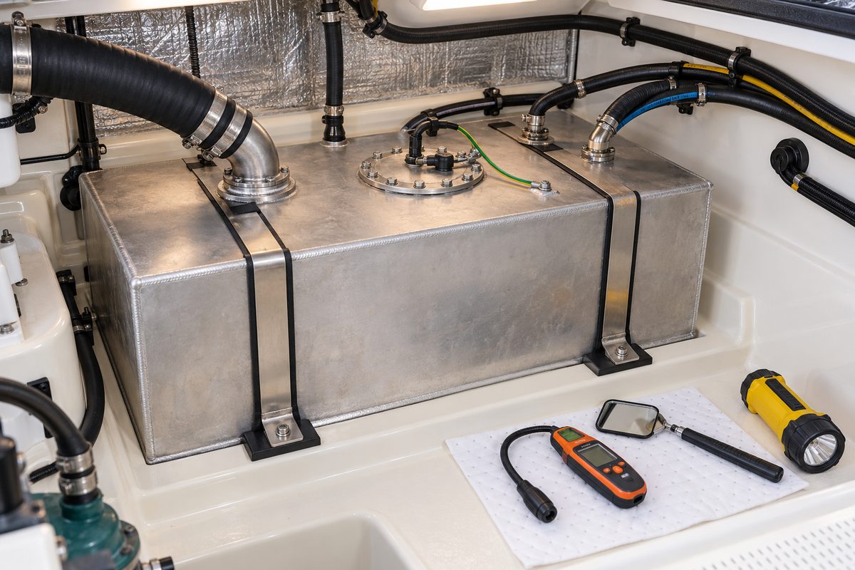
Identify the Tank and Installation Before Inspecting It
Start with the boatbuilder’s fuel-system diagram and the tank manufacturer’s label. Record:
- boat make, model, hull identification number, and engine hours;
- tank manufacturer, model, serial number, material, capacity, and production date;
- gasoline or diesel fuel specification;
- number and location of tanks;
- fill, vent, withdrawal, return, crossover, sender, inspection, and pressure-relief fittings;
- installed emissions components such as fill-limit, grade, vent, and pressure-relief valves;
- hold-down strap, bracket, cradle, and support arrangement; and
- the dates of the last fuel-hose, sender-gasket, and tank inspection.
Common tank materials include rotationally molded polymer, aluminum, stainless steel in limited applications, and older coated or galvanized steel. Inspection clues and acceptable mounting methods differ. A polymer tank must be allowed to expand as its manufacturer specifies. An aluminum tank must be protected from trapped moisture, abrasive contact, and incompatible materials. A repair or coating suitable for one material may damage another.
The U.S. Coast Guard’s fuel-system compliance guidance addresses construction and installation requirements for covered gasoline-powered boats, but it is not a substitute for the current federal regulations, ABYC standards, or the tank and boat manuals. Use the standards applicable to the boat’s build date, fuel, and installation.
Prepare the Compartment Safely
Extinguish smoking materials, flames, heaters, and other ignition sources. Disconnect shore power if the boatbuilder’s procedure requires it, stop the generator, and prevent automatic generator start. Do not disconnect batteries until the boat manual’s vapor-control procedure says it is safe; operating a switch in a vapor-rich space can itself create a spark.
Open access panels gently without dragging them across hoses or wiring. Ventilate gasoline-engine and tank compartments with the installed blower when directed, then allow additional natural ventilation. A blower reduces risk but does not prove the space is vapor-free.
Use only lighting and gas-detection equipment rated for the environment. Do not rely on smell alone: human odor sensitivity varies, diesel and bilge odors can mask gasoline, and some modern low-permeation systems behave differently from older vented systems. If a detector alarms, leave the space, prevent operation, and have the system evaluated.
Protect the bilge and waterways. Keep absorbent fuel pads ready, but do not use them as a permanent solution for an active leak. Contaminated absorbents and fuel must be handled under local rules.
Inspect the Compartment Before the Tank
The compartment often reveals the failure before the tank does. Look for:
- a clean or dark “tide line” showing that water has stood against the tank;
- fuel sheen, wetness, staining, softened paint, or swollen sealant;
- persistent odor concentrated near one corner or fitting;
- rust flakes or white aluminum-corrosion products beneath the tank;
- black rub dust from a moving strap or chafing pad;
- loose fasteners, broken tabbing, cracked supports, or shifted shims;
- debris trapped beneath a tank;
- blocked limber holes or drains;
- water dripping from deck hardware, cup holders, hatches, or plumbing above; and
- wiring, battery cables, or equipment that can contact the tank.
Trace water to its source. Replacing a corroded tank without stopping the leak above it recreates the failure. Likewise, a dry bilge on inspection day does not erase a ring of corrosion left by repeated wetting.
Do not drill, grind, sand, vacuum with ordinary equipment, or use a wire brush around a fuel tank or vapor space. A spark, hot particle, or static discharge can ignite vapor. Even a tank described as “empty” can contain an ignitable mixture.
Check Supports, Straps, Brackets, and Expansion Clearance
A permanent tank must remain secure under acceleration, deceleration, wave impact, and trailering of the boat, while its installation avoids point loads and abrasion. Inspect every visible support and hold-down.
Look for:
- a tank that shifts when the boat moves or when light hand pressure is applied from a safe access point;
- loose strap fasteners or distorted brackets;
- sharp strap edges cutting into the tank;
- missing, compressed, soaked, or displaced cushioning;
- corrosion under a strap or where dissimilar metals meet;
- a support that carries the tank on a narrow ridge instead of the intended surface;
- mounting hardware that has pulled from a bulkhead or deck;
- foam or sealant that traps water against metal;
- expansion clearance that has disappeared as hoses, walls, or added equipment moved; and
- contact marks at corners, seams, baffles, fittings, or sender plates.
Moeller’s current permanent polymer-tank guidance says the tank must be fully supported, secured against bouncing and chafe, and allowed to expand in all directions by the amount specified for that product. Its published example uses 3 percent clearance for hydrocarbon expansion. That figure applies to the cited Moeller tank guidance; do not impose it on an aluminum tank or a different polymer product without its documentation.
Hold-downs should restrain the tank without crushing it. Do not tighten a strap simply because it appears loose. First identify the tank material, intended pad, bracket geometry, and manufacturer instructions. An over-tightened strap can deform a polymer tank, concentrate stress, or damage a seam.
Inspect Accessible Tank Surfaces
Use a bright approved light and inspection mirror to examine as much of the tank as the installed access permits. A borescope should be used only if it is rated for the vapor environment and cannot damage a hose or surface.
On aluminum tanks, watch for:
- white powdery corrosion;
- pitting, especially beneath straps, pads, foam, labels, and standing water;
- dark pinpoints or weeping trails;
- corrosion at welds, brackets, and fittings;
- paint or coating that is blistered or undermined; and
- copper or brass components touching bare aluminum.
On steel tanks, look for coating failure, rust scale, seam corrosion, and thinning. On polymer tanks, inspect for abrasion, cuts, deformation, deep discoloration, cracking, melted areas, fitting distortion, and loss of clearance. A molded line or shallow surface mark is not automatically a crack, but any change that is wet, spreading, or paired with odor requires evaluation.
Do not scrape corrosion to “see how deep it goes” while the tank is installed and contains fuel. Cleaning can open a pinhole. A qualified shop can determine whether the tank needs controlled cleaning, thickness measurement, pressure testing, removal, or replacement.
Examine Every Accessible Fitting and Seal
Tank-top fittings often fail before the tank shell. Inspect the fuel sender, pickup or withdrawal fitting, return fitting on diesel systems, fill connection, vent connection, crossover plumbing, inspection plate if fitted, and emissions valves.
Look for:
- dampness, staining, varnish, dust stuck to a seep, or softened sealant;
- a sender flange that is warped or unevenly tightened;
- cracked, flattened, squeezed-out, or fuel-softened gaskets;
- a fitting that has rotated or is carrying hose weight;
- corrosion around screws, studs, and terminals;
- a missing protective boot on a sender terminal;
- loose anti-siphon or withdrawal components;
- a hose barb that is not fully engaged; and
- added fittings, plugs, or adapters not shown in the original plan.
Do not tighten a fitting by feel. Tank fittings can crack, strip, rotate inside molded material, or damage a welded boss. Use published torque and sealing procedures. Moeller states that a tank should be pressure-tested after fittings are moved; that does not authorize an owner to pressurize an unknown tank.
Sender inspection should remain external unless the tank manual provides a safe removal procedure and the space has been made safe professionally. Removing a sender opens the tank directly to the compartment and can release vapor. It also creates a new gasket-sealing job.
Inspect Fill, Vent, Supply, and Return Hoses
This article focuses on the fixed tank and its immediate connections; a complete fuel-hose service may require a separate inspection. Examine the accessible hose from each tank fitting far enough to confirm that the connection is supported and unstressed.
Check for:
- cracked, hardened, sticky, swollen, blistered, or chafed hose;
- exposed reinforcement or a cut outer cover;
- an expired or inappropriate hose specification;
- a bend that can kink as the tank expands;
- sagging that traps fuel in a vent line;
- a fill hose pulling sideways on the tank neck;
- clamps placed off the barb or cutting the hose;
- corrosion, missing screws, or perforation on clamps;
- metal hose supports that abrade the cover; and
- fuel lines routed against batteries, exhaust, moving machinery, or sharp structure.
Fill and vent systems on newer emissions-controlled boats can include pressure-relief, anti-spitback, grade, and fill-limit valves. Do not remove a valve because filling has become slow. Diagnose the complete system using the boatbuilder and component instructions.
Perko’s vent instructions call for compliant hose attachment and pressure testing after installation. The exact hose size, number and position of clamps, valve orientation, and test procedure remain product-specific.
Check Grounding, Bonding, and Sender Wiring Without Guessing
Metallic fill components and fuel-system parts may require a grounding path to control static electricity. The fuel-level sender also needs secure, protected wiring. These functions are related but not interchangeable with the boat’s cathodic bonding system.
Inspect accessible conductors for broken strands, corrosion, loose support, chafe, heat, non-marine splices, and terminals attached over paint or oxidation. Do not add a wire between the tank and the bonding network simply because a metal tank appears ungrounded. Follow the boat’s wiring diagram and applicable standards.
With gasoline systems, electrical testing in or near the tank compartment requires ignition-protected tools and a verified safe atmosphere. Continuity and resistance tests, sender diagnosis, and repairs should be performed by a qualified marine technician when the circuit’s purpose or safe test point is uncertain.
Do Not Perform an Improvised Pressure Test
Pressure testing can locate leakage at fittings and tank seams, but an incorrect test can rupture the tank, damage emissions valves, distort a polymer tank, or spray fuel. Never connect unregulated shop air, plug the vent blindly, or use an automotive smoke machine on a marine tank.
The correct procedure depends on tank material, design pressure, installed valves, fuel type, and applicable standards. Moeller’s cited installation instructions describe a low-pressure test for particular tanks and tell an unfamiliar owner to seek professional assistance. That number is not a universal target.
A qualified technician can isolate or protect valves, use a calibrated low-pressure source, monitor pressure, apply an approved leak-detection solution, and document results. The tank may need to be drained, purged, or removed before repair. Welding or brazing a used fuel tank requires a specialist; simply rinsing it does not make it safe.
Decide How to Store the Fuel by the Engine and Tank Manuals
Fuel-level recommendations differ. Some manufacturers prefer reducing empty vapor space; others account for polymer expansion, emissions-system behavior, weight, ethanol blend, long storage, or tank service planned during layup. Do not adopt a universal “full” or “empty” rule.
Use fuel of the specification allowed by the engine and boat. If stabilizer is recommended, use a product approved for the fuel and engine, measure it accurately, add it at the correct time, and run the engine or generator long enough to distribute treated fuel according to its manual. Stabilizer cannot reverse phase separation, remove water, repair a leaking tank, or make old contaminated fuel fresh.
Record the approximate tank level and fuel source. If water or contamination is suspected, have a sample drawn safely from the correct low point or filter system. Do not open a tank fitting simply to insert an unapproved suction hose.
Recommission Before the First Spring Start
Before energizing equipment or starting an engine:
- Open the compartment and inspect for odor, liquid fuel, water, or shifted components.
- Ventilate by the boatbuilder’s procedure.
- Confirm hold-downs, access covers, hoses, wiring, and fittings remain undisturbed.
- Restore any disconnected sender or monitoring circuit through the documented procedure.
- Verify extinguishers and vapor-detection equipment are ready.
- Operate the blower for the prescribed time on gasoline-powered boats.
- Check the bilge and tank compartment again before starting.
- Start the engine and inspect accessible fittings and hoses without placing yourself near rotating or hot machinery.
- Watch the fuel gauge and engine behavior for unexpected changes.
- Reinspect after the first fueling, because a high fuel level can expose leaks above the normal winter level.
Stop for fuel odor, sheen, dampness, vapor alarm, erratic fuel delivery, or an unexplained gauge change.
Fixed Marine Fuel Tank Inspection Checklist
- Identify tank manufacturer, material, capacity, label, and installed components.
- Review the boat, tank, and emissions-system manuals.
- Eliminate ignition sources and ventilate by the boatbuilder’s procedure.
- Inspect the compartment for water paths, odor, stains, rub dust, and debris.
- Check supports, straps, brackets, pads, fasteners, and expansion clearance.
- Inspect accessible tank surfaces without scraping or power tools.
- Examine sender, pickup, return, fill, vent, crossover, and valve fittings.
- Check nearby hose condition, clamp placement, support, and strain.
- Inspect grounding, bonding, and sender wiring against the original diagram.
- Stop and arrange professional service for any fuel, vapor, or active seep.
- Use only the manufacturer-approved pressure-test procedure.
- Store fuel according to the engine, tank, and boat manuals.
- Reinspect before starting and again after the first spring fueling.
Record Fuel-Tank Maintenance in BoatDuty
Create a BoatDuty entry with the inspection date, engine hours, tank manufacturer and material, label information, capacity, approximate fuel level, fuel type, stabilizer product and amount if used, accessible surfaces examined, water or corrosion locations, strap and pad condition, hose markings, sender and fitting observations, odor or detector results, pressure-test report, technician, repairs, and planned follow-up.
Photos of the tank label, each fitting, the underside of straps, and any corrosion pattern make future inspections far more useful. A precise history can show whether a stain is old, a rub mark is growing, or an aluminum pit has changed between seasons.
Sources
- U.S. Coast Guard, Boatbuilder’s Handbook—Subpart J: Fuel Systems (33 CFR 183.501–183.590 compliance guidance)
- U.S. Coast Guard, Federal Regulations for Boats and Associated Equipment (current links to fuel-system and ventilation regulations)
- Moeller Marine, Emissions-Related Permanent Fuel Tank Installation Instructions (support, secure mounting, chafe protection, fitting access, and polymer expansion)
- Moeller Marine, Permanent Fuel Tank Installation Kit Instructions (fittings, grounding, and model-specific leak testing)
- Moeller Marine, Tank Cradle Hold-Down Kit Instructions (strap fit and material-specific clearance)
- Moeller Marine, Permanent Fuel Tank FAQs (installation, access, fitting movement, odor, and professional pressure testing)
- Perko, Fig. 0592 Tank Vent Installation Instructions (vent mounting, hose attachment, and pressure-test requirement)