

A boat fuel gauge that stays on empty, remains pinned on full, jumps with every wave, or disagrees with the fuel you added does not automatically need a new sender. The fault may be in the gauge, wiring, ground, connector, network interface, sender, float movement, calibration, or even the shape of the tank.
End-of-season troubleshooting is a good time to document the system and isolate the problem without the pressure of a departure deadline. It is also work that demands strict gasoline-vapor precautions. Any test at a tank opening can expose fuel and vapor, and an ordinary switch, meter connection, drill, shop light, or power tool can become an ignition source. Keep diagnosis noninvasive until the boat and sender manufacturer's procedures justify more.
This guide covers conventional resistive marine senders and gauges, plus the initial checks that also apply to electronic and NMEA-connected systems. It does not provide a universal resistance range or mounting procedure because several standards and sender technologies are in use.
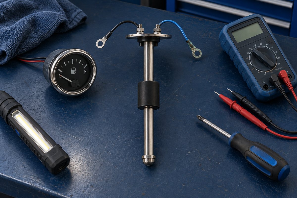
Learn Which Fuel-Level System the Boat Uses
Start at the tank and helm documentation. Common arrangements include:
- A swing-arm resistive sender with a pivoting float.
- A vertical reed-style sender with a float that slides on a tube.
- A capacitive or ultrasonic sensor.
- A resistive sender connected to an analog gauge.
- A sender connected to an engine gateway, tank monitor, or multifunction display.
- Multiple tanks selected by a switch or configured electronically.
Record the sender manufacturer, model, length, mounting pattern, number of terminals, resistance or output standard, tank material, tank shape, gauge model, and system voltage. Photograph every connection before changing it.
Do not assume that a replacement sender and gauge are compatible because both are labeled “marine.” For example, KUS documents a common American 240-to-30-ohm sender range, while other products use different curves. Some gauges are programmable; others are fixed. A mismatched gauge and sender can move in the wrong direction or report an inaccurate level even when both parts are functional.
Separate Normal Fuel Movement From a Fault
Fuel sloshes as the boat accelerates, turns, trims, or rocks. Some gauges damp that movement; others respond quickly. A tank with sloped sides, a V-bottom, baffles, or an irregular shape does not convert liquid height into gallons linearly. Half the tank's height may not equal half its capacity.
Before diagnosing, record when the symptom occurs:
- Only underway or also at rest.
- With the ignition or instrument circuit on, off, or changing state.
- On one tank or every selected tank.
- At a particular fuel level.
- After rain, fueling, maintenance, or battery work.
- Constantly, intermittently, or only after vibration.
Compare the indication on level ground or at a consistent floating attitude. Use fuel purchased and engine fuel-flow records as supporting information, not as a reason to assume the gauge is exact. Never intentionally run a boat out of fuel to “calibrate” the empty point.
Work Safely Around the Fuel Tank
Before touching tank wiring or an access plate:
- Extinguish smoking materials and all flames.
- Shut down engines, generators, chargers, and unneeded electrical equipment.
- Follow the boatbuilder's ventilation procedure.
- Isolate the applicable circuit before disconnecting wires.
- Use equipment and lighting suitable for the space.
- Keep sparks, static discharge, and hot tools away from gasoline vapor.
The U.S. Coast Guard Boatbuilder's Handbook explains ignition-protection requirements for electrical components near gasoline fuel sources. Preserve the approved installation. Do not replace an ignition-protected or sealed component with a generic automotive part, and do not make live jumper connections at an open gasoline tank.
Removing a sender from a gasoline tank is not a casual next step. The KUS installation guidance calls for emptying tanks of fuel and fumes before installation work. If you cannot positively establish safe conditions and follow the boat's procedure, stop and use a qualified marine technician.
Inspect Before Measuring
With power isolated, inspect the accessible sender top, wire run, gauge terminals, connectors, and grounds. Look for:
- Green corrosion at a ring terminal or stud.
- A loose nut, rotated stud, or cracked insulating washer.
- A missing terminal boot or protective cover.
- Brittle insulation, chafe, crushed wire, or an unsupported harness.
- Water tracks from a leaking deck fitting or access hatch.
- Fuel staining, odor, dampness, or a deteriorated sender gasket.
- Heat discoloration at a connector or gauge.
- An added splice, selector switch, or network converter not shown on the original diagram.
- A ground shared through corroded hardware instead of the specified conductor.
Do not tighten a sender terminal by twisting the internal stud. Hold hardware only as the manufacturer directs, and use the specified torque. Overtightening can damage the insulator or sender top. If fuel odor or staining suggests leakage, do not energize the circuit until the leak is evaluated.
Confirm Gauge Power and Ground First
A traditional analog gauge usually needs switched power, ground, and a sender signal. Illumination may have a separate feed. An electronic display may receive tank data through a module or network instead.
Use the gauge wiring diagram to verify supply voltage and ground at the correct terminals. Measure under the conditions in which the fault occurs; an unloaded wire can show normal voltage through a corroded connection yet fail when the gauge draws current. Inspect the fuse, breaker, ignition feed, splice, connector, and ground bus.
If several gauges fail together, look for a shared power or ground problem before testing every sender. If only one selected tank misbehaves, compare the selector wiring or channel configuration. Do not move wires among terminals simply to see what happens; a wrong connection can damage the gauge or gateway.
Test the Signal Circuit Methodically
Manufacturer troubleshooting procedures often isolate the gauge, signal wire, and sender in sequence. Follow the instructions for the exact gauge because the response to an open or grounded signal varies by design.
For a conventional resistive system, a technician may:
- Verify gauge supply and ground.
- Disconnect the sender signal with circuit power off.
- Check the signal conductor for continuity and shorts.
- Measure sender resistance only after isolating it from the gauge and ground as directed.
- Compare the result with the sender's specified curve and the known liquid level.
KUS publishes both a sender troubleshooting guide and expected readings for its sender families. Faria Beede publishes installation sheets and gauge-test guidance. Those values are product-specific. Do not assume 240-to-30 ohms, 10-to-180 ohms, or any other curve without identifying the parts.
Never use a meter's resistance mode on an energized circuit. Do not short a sender wire at an open gasoline tank or use an unprotected jumper as a substitute for the manufacturer's test. If a procedure calls for moving the float outside the tank, complete all fuel-vapor safety steps first.
Distinguish Common Symptom Patterns
Gauge always reads empty
Possible causes include loss of gauge power, poor gauge ground, an open signal wire, corroded sender connection, stuck or failed sender, incompatible resistance curve, or configuration error. Some gauge designs respond differently to an open circuit, so confirm the manual before drawing a conclusion.
Gauge always reads full
A signal conductor shorted to ground can drive some systems toward full, while a sender or gauge fault may create the same display. Again, the direction depends on the gauge design. Inspect the wire where it passes metal edges and where previous work may have pinched it.
Gauge is erratic
Loose terminals, intermittent grounds, water in a connector, worn swing-arm resistance elements, a sticking float, broken baffle contact, and ordinary slosh can all cause movement. Tap-testing parts or wiggling live wiring around gasoline vapor is unsafe. Instead, isolate power, inspect, and reproduce the symptom through the approved diagnostic method.
Gauge changes but is inaccurate
Check sender/gauge compatibility, sender length, float travel, tank shape, mounting orientation, calibration settings, and whether the display is configured for the correct tank. A sender can accurately report liquid height while the display's gallon estimate remains wrong because the tank profile is not linear.
Inspect Sender Movement Only Under Safe Conditions
A swing-arm float can bind against a baffle, tank wall, hose, or pickup tube if the arm is the wrong length or orientation. A vertical sender float can stick because of contamination, damage, an incorrect stop, or incompatibility with the liquid. Electronic senders can fail without visible movement problems.
Do not remove the sender solely because the gauge is inaccurate. First prove the power, ground, signal path, compatibility, and configuration. If removal is required, follow the boatbuilder and sender instructions for draining, ventilating, opening, and resealing the tank. Mark the original orientation before lifting the unit and avoid bending the float arm as it exits.
Once safely removed, check that the float moves freely through its intended travel without scraping or sticking. Inspect the tube, arm, pivot, stops, terminals, flange, and gasket surface. Keep dirt, gasket fragments, and tools out of the tank.
Match the Replacement Correctly
A correct replacement must match more than tank depth. Verify:
- Fuel compatibility and marine application.
- Output or resistance curve.
- Gauge, gateway, or display compatibility.
- Tank depth and the maker's specified sender length.
- Swing-arm travel and clearance, if applicable.
- Mounting pattern and flange orientation.
- Terminal arrangement and grounding method.
- Tank material and gasket compatibility.
- Ignition-protection and regulatory requirements for the location.
Many marine senders use an asymmetrical five-hole SAE mounting pattern. It fits only in the correct rotational position. Do not force screws into a misaligned pattern, redrill a tank top, or substitute longer screws that may damage the tank. Use the supplied or specified gasket, hardware, sealant policy, tightening sequence, and torque.
If the tank flange, threads, or top surface is corroded or distorted, the repair may exceed a sender replacement. A fuel-system professional should evaluate structural damage and sealing integrity.
Reinstall Without Creating a Leak
Clean the mating surface using the approved method and prevent debris from falling into the tank. Confirm the gasket is oriented correctly and the sender float or tube has unobstructed travel. Start all screws by hand in the correct pattern. Tighten gradually and evenly to the manufacturer's specification.
Do not apply a generic sealant unless the sender or tank maker approves it for the fuel, gasket, and materials. Excess sealant can squeeze into the tank or interfere with grounding and gasket compression.
Reconnect the signal and ground exactly as documented, support the harness, restore protective boots, and close the access area. After fueling, inspect the sender flange and nearby fittings for leaks under the conditions specified by the boatbuilder. A dry bench test does not prove the tank seal.
Calibrate and Verify the Reading
Programmable displays may offer tank-type, capacity, sender-curve, or multi-point calibration settings. Follow the display and sender manuals. Entering tank capacity alone does not correct a non-linear shape unless the system supports a profile or calibration points.
Verify at several known fuel levels over normal use. Record the boat's attitude and gallons added. Treat the fuel gauge as one input to fuel planning, not a substitute for reserve calculations and actual consumption history.
Winter Storage Considerations
Complete the boatbuilder and engine manufacturer's fuel-storage procedure, including the correct treatment of fuel, tanks, filters, and ventilation. This article does not prescribe whether a particular tank should be stored full or empty; that decision depends on tank material, fuel, emissions equipment, climate, and manufacturer guidance.
Leave sender wiring supported and protected from condensation. Correct leaking hatches or deck fills that drip onto the sender. If a sender has been removed, do not leave the tank temporarily covered for winter—complete the approved sealed repair before storage.
Fuel Sender and Gauge Checklist
- Record sender, gauge, tank, system voltage, and output standard.
- Document the symptom at rest, underway, and at known fuel levels.
- Isolate ignition sources and follow gasoline-vapor precautions.
- Inspect sender terminals, gasket area, wiring, connectors, and grounds.
- Stop if fuel odor, staining, dampness, or a damaged tank surface is found.
- Verify gauge power and ground under the maker's test conditions.
- Test the signal conductor before condemning the sender.
- Measure resistance only on a de-energized, isolated circuit.
- Use the exact sender curve and gauge response from product documentation.
- Remove the sender only after safe tank preparation.
- Match replacement length, pattern, output, materials, and application.
- Reinstall with the specified gasket, hardware, sequence, and torque.
- Inspect for leaks and verify readings at multiple known levels.
Keep a Useful BoatDuty Record
In BoatDuty, record the sender and gauge model numbers, tank capacity and shape, resistance or output standard, sender length, wiring colors, test readings, known fuel level, calibration settings, gasket and hardware used, leak-check date, and repairs made. Add photos of the original terminal layout and flange orientation before disassembly.
That record prevents the next diagnosis from starting with guesses. It also helps explain why a gauge may be repeatable but not perfectly linear—and whether a future change is a new fault or the same tank geometry you documented today.