

Boat engine hatch lift maintenance before storage helps ensure the hatch opens reliably when the batteries are weak, access is urgent, or spring recommissioning begins. Hatch-lifting systems work under substantial load and often operate in a damp engine-compartment environment. A worn clevis pin, loose mounting bracket, leaking hydraulic fitting, corroded electrical connection, or dirty piston rod can turn a convenience feature into a safety hazard.
The inspection is especially valuable before winter because the hatch may remain closed for months. Corrosion can progress unnoticed, hydraulic leaks can drain a reservoir, and a partially discharged battery can conceal a marginal motor or connection. A careful fall check establishes whether the system is ready for storage or needs repair while the boat is accessible.
Not every powered hatch uses the same mechanism. Systems may use a self-contained electric linear actuator, an electro-hydraulic pump and cylinder, a hydraulic cylinder tied into another onboard power unit, gas springs with an electric lift, or multiple synchronized actuators. Follow the exact boat and lift-system manuals; service requirements, fluids, limit switches, emergency release methods, and load ratings are model-specific.
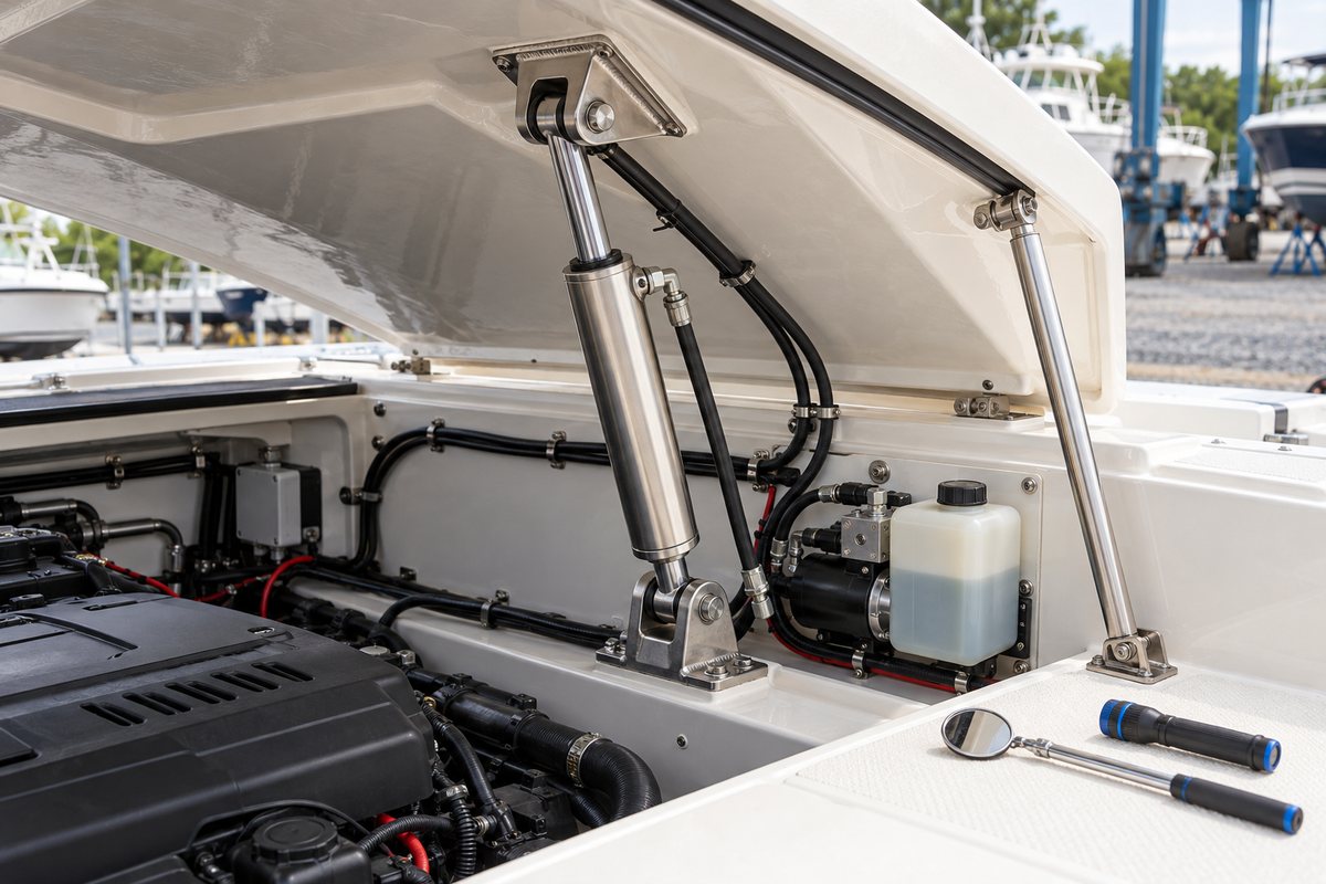
The first rule: support the hatch independently
An open engine hatch stores considerable potential energy. The actuator, gas spring, hydraulic pressure, or control switch is not a safe work support.
Before placing any part of your body under the hatch:
- Shut down engines and generators and remove ignition keys.
- Turn off the hatch-lift circuit using the documented disconnect or breaker.
- Install the boatbuilder’s mechanical safety prop, service lock, or an appropriately rated rigid support.
- Confirm the support bears on strong structural points and cannot slip.
- Keep controls inaccessible so nobody can move the hatch during inspection.
Do not use a loose board, a hydraulic cylinder alone, or a gas spring as the only protection against the hatch falling. If the boat has no safe service-support method, have the yard or boatbuilder establish one before maintenance continues.
Also identify the emergency-opening procedure before a failure occurs. Some systems have a removable clevis pin, manual release, access port, remote terminals, or alternate method for powering the actuator. Verify the manual rather than experimenting with a loaded mechanism.
Identify the lift system and its service information
Find the actuator, pump, reservoir, relay or reversing module, circuit protection, control switch, upper and lower mounts, and any secondary cylinder or gas spring. Record the manufacturer and part numbers.
The manual should answer several important questions:
- Maximum lift load and approved mounting geometry
- Required supply voltage and circuit-protection rating
- Whether internal limit switches stop travel automatically
- Whether the switch must be released immediately at full travel
- Approved hydraulic-fluid type, if applicable
- Reservoir-level checking position
- Bleeding procedure
- Piston-rod cleaning or lubrication instructions
- Service interval for hydraulic oil or other components
- Emergency or manual-release procedure
Do not apply a generic lubricant to a piston rod, seal, screw drive, or gas spring unless the manufacturer calls for it. Some products are designed to run clean and dry, and the wrong lubricant can attract grit or damage seals.
Inspect the hatch, hinge, and load path
The lift mechanism cannot compensate for a binding hatch.
With the hatch safely supported and the lift circuit off, inspect the hinge line, surrounding laminate or metal structure, and hatch frame. Look for loose hinge fasteners, cracked gelcoat, compressed core, distorted brackets, or signs that the hatch has shifted. Check weather seals and drains for debris that could make the hatch stick.
Move the hatch only as the approved support arrangement permits. It should follow its intended arc without the actuator, hose, cable, or bracket approaching a hard edge. A hatch that rubs the deck, twists, or needs unusual force can overload an otherwise healthy lift.
Pay particular attention to the actuator’s mounting geometry. Both attachment points should remain aligned through the full stroke. Side loading can score a rod, wear bushings, loosen fasteners, and damage seals.
Check pins, clevises, brackets, and fasteners
Inspect every upper and lower mounting point.
Look for:
- Missing cotter pins, retaining clips, circlips, or locking hardware
- Clevis pins working out of their brackets
- Elongated holes or worn bushings
- Cracked welds or bent tabs
- Corrosion between dissimilar metals
- Loose fasteners or movement in the backing structure
- Brackets pulling away from fiberglass or crushing a cored panel
- Contact marks showing that the actuator reaches a bracket or hard stop
Do not substitute an ordinary bolt for a designed pivot pin without manufacturer approval. A pivot must allow the intended movement without threads cutting into the bearing surface. Replace missing retainers with the specified parts.
If tightening is required, use the boatbuilder’s or lift manufacturer’s torque and bedding guidance. Excess torque can crush laminate, deform a bracket, or bind a pivot.
Inspect an electric linear actuator
A self-contained electric actuator typically combines a DC motor, gearbox, screw mechanism, internal or external limit controls, and an extending tube or rod.
Inspect the body for corrosion, cracked housings, water entry, loose end caps, or a bent tube. Check the rod or extension tube for scoring, rust, dirt, and a film of leaking lubricant. Examine the cable where it enters the actuator and where it flexes during hatch travel.
Trace the wiring to the breaker or fuse, control switch, relay, and ground connection. Look for:
- Green corrosion or salt deposits at terminals
- Loose crimp lugs or unsupported harnesses
- Chafe at bulkheads and hinge areas
- Heat-discolored connectors
- Water trapped in low connectors
- Non-marine splices in the engine compartment
- Wiring routed where the hatch or actuator can pinch it
The actuator and electrical components installed in a gasoline engine space must meet the applicable ignition-protection requirements. Do not replace them with an automotive or household actuator that merely fits the mounting points.
Inspect an electro-hydraulic lift
Hydraulic systems add a pump, reservoir, valves, hoses, fittings, and one or more cylinders.
Clean the visible cylinder rod with the method specified by the manufacturer. VETUS instructs owners of its electro-hydraulic lifting system to inspect the piston rod regularly and clean away dirt to protect the oil seal. Look for scoring, pitting, corrosion, or an oily ring that returns after cleaning.
Inspect the cylinder body, rod seal, hose crimps, threaded fittings, pump, manifold, and reservoir for wetness. A film of oil attracts dirt, so distinguish old residue from an active leak by cleaning the area and rechecking after a controlled cycle.
Check the reservoir only with the hatch and actuator in the position specified by the manual. Fluid level can change with cylinder position. Use only the named fluid; mixing an unknown oil into the system can affect seals and operation.
VETUS specifies regular oil-level checks for its EHP lifting system and calls for hydraulic-oil replacement every two years or 200 operating hours for that particular product. Treat that as model-specific guidance, not a universal interval. Bennett’s hatch-lifter installation instructions call for cycling the system to purge air, rechecking reservoir level, and inspecting connections for leakage. Follow the procedure for the installed unit.
Replace damaged hydraulic hose rather than covering a wet or abraded spot. Do not use hands to search for a pressurized leak.
Test operation and listen to what the system tells you
Remove tools from the travel path, stand clear, and remove the independent support only when ready for a controlled operational test. Restore power according to the manual.
Operate the hatch through one complete opening and closing cycle while watching from a safe position. Check for:
- Smooth travel without shuddering, hopping, or twisting
- Consistent speed in both directions
- Brackets that remain aligned without flexing
- Hoses and wires that remain clear through the entire arc
- Automatic stopping at the correct endpoints when limit switches are fitted
- Prompt release of the control at full travel when the design has no limit switches
- No pump cavitation, relay chatter, grinding, or laboring motor sound
- No new oil at seals or fittings
- A hatch that remains in the intended position without creeping
VETUS warns that, when limit switches are not fitted, the operator should release the control immediately after full extension or retraction to prevent the electro-hydraulic pump from overheating. Do not hold the switch after motion stops just to see whether the motor will continue.
If the hatch moves slowly, do not assume the actuator is worn out. Low battery voltage, voltage drop, a poor ground, undersized wiring, a failing relay, air in a hydraulic system, binding hinges, misaligned mounts, or excessive hatch weight can produce similar symptoms.
Diagnose symptoms without creating a new hazard
Stop and arrange repair if:
- The hatch cannot be secured independently
- A mount, hinge, or fiberglass support is cracked or moving
- A clevis pin or retainer is missing
- The actuator rod is bent, deeply scored, or corroded
- Hydraulic oil is actively leaking
- The hatch creeps downward after stopping
- The motor runs but the hatch does not move
- A breaker trips repeatedly
- Wiring or terminals show heat damage
- The hatch binds, twists, or contacts the actuator
- The system reaches the end of travel but continues to strain
- The installed actuator or electrical component lacks required ignition protection
Do not bypass a limit switch, install a larger fuse, or jump a control circuit as a shortcut. Those changes can remove protection while leaving the mechanical fault in place.
Prepare the hatch lift for winter storage
After the inspection, clean the compartment and remove anything that could jam the mechanism in spring. Set the hatch in the storage position recommended by the boatbuilder. A slightly open hatch may improve ventilation on some stored boats, while other installations must remain fully closed to keep water out or maintain cover fit.
Confirm the normal manual-release hardware, service prop, or emergency access tool remains aboard and accessible. Do not leave a temporary support in place unless the boatbuilder approves it for long-term storage.
If the batteries will be disconnected, think through how the hatch will be opened later. A power-off hatch can block battery or engine access. Record the emergency-opening method and keep any required external leads or tools reachable from outside the closed compartment.
Boat engine hatch lift maintenance checklist
- Identify the actuator, pump, controls, and exact model numbers
- Retrieve the boatbuilder and lift-system manuals
- Record the emergency-opening or manual-release procedure
- Shut down machinery and isolate the lift circuit
- Support the hatch with an approved independent mechanical support
- Inspect hinges, structure, seals, drains, and hatch alignment
- Check brackets, backing, pins, bushings, and retaining clips
- Inspect actuator body, rod, seals, and travel clearances
- Inspect wiring, circuit protection, relays, grounds, and chafe points
- Inspect hydraulic pump, reservoir, hoses, fittings, and fluid level if fitted
- Use only model-approved fluids, parts, lubricants, and torque values
- Cycle the hatch once while watching every moving connection
- Check for binding, noise, leaks, heat, slow movement, and drift
- Confirm the proper winter storage position
- Keep emergency access equipment reachable
Record the work in BoatDuty
Log the inspection date, actuator and pump models, battery voltage during the operational test, hydraulic-fluid type and level if applicable, any leak or corrosion locations, parts replaced, and the emergency-opening method in BoatDuty. Note whether the hatch was left open or closed and whether the batteries will remain connected.
Photos of mounting points and hose or cable routing create a valuable baseline. If a bracket moves, a rod begins to pit, or a leak appears next season, the earlier record makes the change easier to recognize.
Supporting sources
- VETUS, electro-hydraulic lifting system installation and operating manual, including piston-rod cleaning, oil-level checks, endpoint operation, and model-specific oil-change guidance
- VETUS product documentation and manuals
- Bennett Marine, hatch-lifter installation instructions, including bleeding, reservoir-level, and leak-check procedures
- Bennett Marine, hatch-lifting systems overview and documentation links
- Bennett Marine technical resources and owner/install manual library