
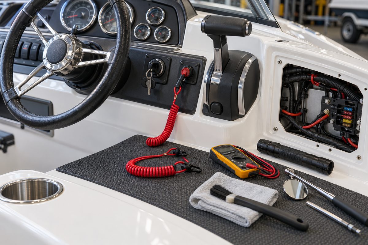
A boat engine cutoff switch is small enough to disappear beside the ignition key or throttle control, yet it can stop a runaway boat when the operator is displaced from the helm. The traditional system uses a coiled safety lanyard and a molded clip that holds or actuates the switch. Wireless systems replace the cord with a fob or wearable link, but the goal is the same: interrupt propulsion when the operator is no longer in control.
End-of-season maintenance should confirm that the switch, lanyard or wireless link, wiring, and engine shutdown function remain dependable. A faded cord, cracked clip, corroded switch, weak fob battery, or bypassed circuit can make the device look present while leaving it unable to work. Testing must follow the boat and engine manuals, with the boat secured and the engine supplied with cooling water. Never start or run an engine dry merely to test the cutoff switch.
Understand the System and the Federal Requirement
The U.S. Coast Guard defines an Engine Cut-Off Switch, or ECOS, as a mechanism that shuts down propulsion when the operator is displaced from the helm. The Engine Cut-Off Switch Link, or ECOSL, connects the operator to that switch. It is usually a coiled lanyard but can be an electronic fob.
Federal rules generally require operators of covered recreational vessels under 26 feet to use an installed ECOS link while operating on plane or above displacement speed, with specific exemptions such as a main helm inside an enclosed cabin. The Coast Guard’s current FAQ explains that covered boats built beginning in January 2020 must have the system maintained in working condition for the life of the boat. State requirements can be broader, and the Coast Guard recommends using a working system even when a particular older or larger boat is outside the federal mandate.
This article is maintenance guidance, not a substitute for reviewing the current federal, state, and local requirements for the boat and operating area.
Identify the Exact Cutoff System
Before testing, record what is installed. Common arrangements include:
- a clip retained beneath a spring-loaded toggle;
- a clip inserted into a push-pull stop switch;
- a lanyard switch integrated into a side-mount control box;
- a tiller-mounted stop switch;
- separate links for twin engines;
- a factory wireless ECOS; or
- an approved aftermarket wireless system.
Find the boat, engine, control, and ECOS manuals. Record the switch or control-box model, engine model and serial number, lanyard part number, and wireless-system model if applicable. Many clips look similar but differ in thickness, shape, retention force, or switch travel. A universal set of molded clips can be useful for diagnosis, but the permanent replacement should be the part specified for the installed system.
If a prior owner removed the switch, taped the clip in place, tied wires together, installed a non-marine toggle, or modified the harness, stop. Restore the safety circuit using the engine and boatbuilder diagrams and appropriate marine components. A bypass is not a repair.
Inspect the Lanyard From End to End
Remove the lanyard only with the engine off and the ignition disabled. Examine the complete coil or cord under good light. Look for:
- cracks, cuts, melted spots, or flattened sections;
- a coil that has hardened, stretched permanently, or lost its retraction;
- ultraviolet fading or chalky plastic;
- corrosion on metal rings or snaps;
- a cracked, distorted, or partly broken switch clip;
- a weak operator-end snap or carabiner;
- knots, tape, zip ties, or splices; and
- a cord so short or long that it cannot function as intended at the helm.
Yamaha’s current safety checklist recommends confirming that the engine safety lanyard is connected and visually in good condition. Replace a questionable cord rather than saving it as a spare. A brittle coil can break before it pulls the clip, while a stretched coil can snag on the wheel, throttle, seat, or passenger.
Check that the operator-end attachment works with actual boating clothing and the D-ring or attachment point on the intended personal flotation device. Do not plan to loop the cord around the throttle, steering wheel, seat, or another part of the boat. The link must leave with the operator.
Inspect the Switch and Clip Interface
Clean around the switch with a dry brush or the product approved by the control manufacturer. Do not flood the switch with solvent, penetrating oil, or contact cleaner unless the manual specifically calls for it. Liquid can wash debris into the switch, attack plastic, or remove internal lubricant.
Inspect the bezel, boot, toggle, push button, retaining groove, and clip-contact surfaces. Watch for:
- cracked or sun-damaged plastic;
- a torn rubber boot;
- looseness in the panel or control box;
- corrosion or green residue;
- a clip that will not seat fully;
- a toggle that sticks or does not return;
- a switch that can be pulled through the mounting hole; and
- signs that the clip has been shimmed or forced.
Insert the correct clip with the engine off. It should seat positively in the orientation shown by the manual. Tug lightly on the lanyard in the direction an operator would move. The clip should release without excessive force, and the switch should move completely into its stop position. Reinstall it and verify that the switch returns correctly. Do not bend the clip to change release force.
If the switch is integrated into a remote-control housing, do not dismantle the housing without its service instructions. Shift and throttle interlocks, trim wiring, ignition circuits, and mechanical adjustments may share that assembly.
Inspect Accessible Wiring and Harness Connections
The cutoff switch commonly stops the engine by opening or grounding a dedicated ignition or engine-control circuit. The logic varies by engine, so never test it by randomly jumping wires.
With power isolated, inspect only the wiring that is safely accessible. Look for chafe, pinched insulation, unsupported harnesses, moisture, corrosion, loose connectors, non-sealed splices, overheated terminals, or wires pulled tight when the throttle or steering moves. Confirm that the harness follows the control manufacturer’s routing and that an access cover cannot cut or crush it.
On multiple-engine boats, determine whether one link stops every propulsion engine or whether each engine has a separate circuit. Do not assume because one engine stops that the complete installation passed. Digital controls and networked propulsion systems can use modules or software logic that require dealer diagnostic procedures.
Replace damaged terminals and wiring by the engine maker’s specifications. Do not substitute an ordinary automotive switch in an exposed marine helm or gasoline-vapor area. Environmental sealing, ignition protection, contact logic, and electrical rating matter.
Perform a Controlled Functional Test
The most important check is whether removing the link actually stops propulsion. Mercury, Yamaha, Honda, and the Coast Guard all direct operators to use or verify the cutoff system according to the product instructions. Honda includes engine-switch and emergency-stop-switch function in its pre-operation checks, while Yamaha recommends confirming that pulling the safety lanyard shuts down the outboard immediately.
Prepare the test carefully:
- Secure the boat so an unexpected engine response cannot move it.
- Ventilate gasoline engine spaces and operate required blowers.
- Put the control in neutral and keep people clear of the propeller and drive.
- Supply cooling water exactly as the engine manual requires.
- Confirm that the lanyard clip is seated and attach the operator end as directed.
- Start the engine using the normal procedure.
- At idle, pull the link in the direction expected during an operator displacement.
- Confirm that every required propulsion engine stops promptly.
- Return the ignition or power control to OFF before reinstalling the clip.
- Verify that the engine restarts only after the link and controls are restored correctly.
Do not increase rpm for this test unless the manual specifically instructs it. Do not pull a lanyard while underway to “see what happens.” If the engine continues running, turn it off normally, isolate power, tag the helm, and arrange repair before the next trip.
Some systems prevent starting when the clip is removed; others permit cranking but inhibit ignition. Follow the actual engine manual rather than treating one behavior as universal. Also distinguish the cutoff switch from a neutral-safety switch. The neutral interlock prevents starting in gear; the ECOS stops propulsion after the operator link disengages. Both should work, but one does not substitute for the other.
Maintain Wireless ECOS Links and Fobs
A wireless ECOS adds components that a cord does not have: operator fobs, batteries or charging contacts, a hub or base module, antennas, pairing data, and audible or visual status indications. Identify the system and follow its manual for:
- fob-battery type and replacement interval;
- charging and storage procedure;
- pairing or enrollment checks;
- maximum number of links;
- low-battery and lost-signal warnings;
- man-overboard activation behavior;
- engine-restart procedure; and
- software or firmware updates.
Inspect the fob housing, wristband, clip, seals, buttons, and battery compartment. Replace swollen, leaking, corroded, or water-damaged batteries and components through the approved process. Do not assume a phone app alone is the ECOS link unless the manufacturer explicitly designed and approved the system that way.
Test each active fob individually. Confirm what happens when the fob is submerged, moves out of range, or is manually activated only through the manufacturer’s safe test method. A wireless system may allow other passengers to remain connected while stopping propulsion for the operator; that behavior must be understood before an emergency.
Keep a Correct Spare Without Defeating the Switch
Carry a spare link specified for the installed switch and store it where a passenger can find it. The spare is for restoring controlled operation after a loss or failure—not for leaving permanently clipped into the switch.
Label the spare by boat or engine if several craft use different clips. Compare its shape and fit during annual service. Keep it out of direct sunlight and away from fuel, solvent, heat, and sharp tools. For wireless systems, store an approved spare fob or battery as directed and include its condition in the pre-departure check.
Make sure regular passengers know where the spare is, how to put the engine in neutral, how to stop the boat, and how to restart after an ECOS activation. Do not wait for an overboard emergency to explain the controls.
End-of-Season Storage
After the functional test, clean and dry the switch and lanyard. Store the primary lanyard in the position recommended by the manufacturer. If it remains at the helm, keep it protected from sunlight, cover pressure, and snagging. Do not leave the coil stretched around the throttle or wheel.
For a wireless system, follow the battery and charging instructions. Some rechargeable products should not be left fully discharged for months, while replaceable cells may need removal if leakage is a concern. Record pairing information without exposing security codes.
Before covering the boat, confirm that the helm cover cannot hold the stop switch in an abnormal position. Keep moisture from collecting around the control box and wiring access. Tag any failed system clearly so the engine cannot be used before repair.
Spring Recommissioning
Repeat the visual inspection and functional test before the first trip. Plastic can crack during cold storage, contacts can corrode, and a fob battery can discharge even if the system passed in fall. Confirm that the correct lanyard is at the helm, the spare is available, wireless links are paired, and every expected engine stops.
Add ECOS use to the departure routine: attach the link before accelerating, give it enough freedom for normal control movement, and confirm it will not snag. The Coast Guard states that the link must be used on covered boats when operating on plane or above displacement speed, while manufacturer guidance may recommend attachment whenever the engine is running. Follow the stricter applicable rule and the equipment manual.
Engine Cutoff Switch and Lanyard Checklist
- Identify the switch, control, lanyard, and wireless-system models.
- Review current federal, state, and local use requirements.
- Inspect the entire cord, coil, switch clip, and operator attachment.
- Replace faded, cracked, stretched, corroded, or improvised parts.
- Inspect the switch bezel, boot, toggle, and clip interface.
- Confirm the correct clip seats and releases normally.
- Inspect accessible harnesses and connectors with power isolated.
- Test every propulsion engine at idle using the manual’s procedure.
- Stop using the boat if removing the link does not stop the engine.
- Check each wireless fob, battery, pairing status, and warning function.
- Carry and label the correct spare link or approved wireless backup.
- Store the lanyard without stretching, sunlight, solvent, or snagging.
- Repeat the functional test before the first spring trip.
Record the Work in BoatDuty
Log the inspection date, boat and engine hours, engine and control models, switch and lanyard part numbers, wireless-system model, fob-battery type and replacement date, wiring findings, and the result for each engine tested. Note how quickly the engine stopped, whether restart required a special sequence, where the spare link is stored, and any parts ordered or repairs completed. A precise BoatDuty record turns the cutoff switch from an easily forgotten red cord into a documented safety system with a repeatable test history.
Sources
- U.S. Coast Guard, Engine/Propulsion Cut-Off Devices FAQ
- U.S. Coast Guard, New Law Requiring Use of Engine Cut-Off Switches
- Mercury Marine, Quick Tip: Lanyard Stop Switch
- Yamaha Outboards, Safety First—Always!
- Yamaha Outboards, Boating Safety Checklist
- Honda Marine, BF25D Operation and Pre-Operation Check Menu
- Honda Marine, BF115D Operation and Pre-Operation Check Menu