

Boat engine-compartment blower maintenance is a small fall task with an important purpose. On gasoline-powered boats, the blower, ducting, vents, wiring, and warning label work together as a ventilation system. A motor that can be heard at the helm does not prove that the pickup duct is intact or that air is actually leaving the boat.
This guide applies primarily to boats with permanently installed gasoline engines—whether for propulsion or electrical generation—and powered ventilation systems. It does not mean every compartment on every boat uses the same arrangement. Diesel installations, open compartments, and boats with model-specific ventilation designs may differ. Identify the equipment and follow the current boat and blower manuals before removing, rewiring, or replacing anything.
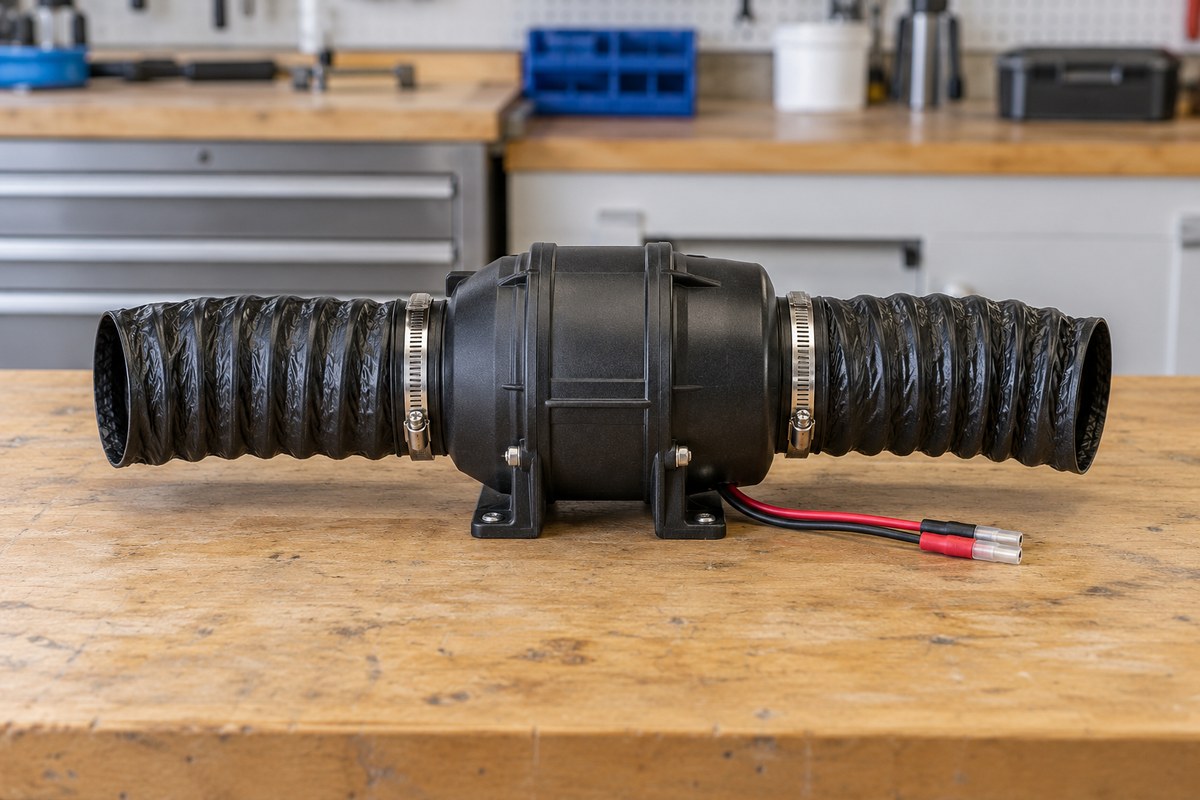
Understand what the blower system is supposed to do
Federal construction requirements apply to boats with gasoline engines used for generation, mechanical power, or propulsion. A compartment containing a permanently installed gasoline engine with a cranking motor must be open to the atmosphere or ventilated by an exhaust-blower system. Where a blower is required, the regulation also specifies placement of its pickup in the lower third of the compartment and above the normal level of accumulated bilge water. 33 CFR Part 183, Subpart K
That design intent helps explain why inspecting only the blower motor is incomplete. A disconnected, collapsed, submerged, or badly routed duct can keep the system from drawing air from the intended area. Likewise, an obstructed discharge vent can reduce flow even when the motor sounds normal.
Do not confuse the ventilation blower with the bilge pump. The pump removes liquid water; the blower moves air and vapors. They have separate components, controls, specifications, and maintenance requirements.
Start with a safe visual inspection
Perform the initial inspection with the engines, generator, battery charger, and other ignition sources off. Allow hot machinery to cool. If you smell gasoline or see a fuel leak, do not energize the blower or other electrical equipment as a troubleshooting step. Keep ignition sources away, open the area only as directed by the boat manual, and have the fuel-vapor problem corrected by a qualified marine technician.
Before touching wiring or the blower itself, isolate electrical power using the manufacturer’s procedure. Rule’s inline-blower instructions specifically call for disconnecting power before work on the unit. Rule 3-inch and 4-inch Inline Bilge Blower Instruction Manual
Use a light suitable for the space and inspect without placing tools where they can fall into moving machinery. Photograph the system before disturbing clamps or ducts so the original routing and wire support are documented.
Inspect the blower housing and mounting
Find every powered blower serving the gasoline engine or generator compartment. Some boats have more than one. Check that each housing is securely mounted and has not shifted against a belt, pulley, exhaust component, or other source of heat and abrasion.
Look for:
- Cracks, melted areas, deformation, or loose housing seams.
- Broken mounting feet, missing fasteners, or enlarged mounting holes.
- Corrosion at fasteners and electrical terminals.
- Evidence that water has entered or repeatedly sprayed the unit.
- Debris at exposed openings or an object contacting the blower wheel.
Do not open a sealed motor or improvise a repair with tape or adhesive. Jabsco’s installation guidance places its flange-mount blower away from extreme heat and spray and calls for even fastener tightening to avoid flange damage. Those details are model-specific, but they illustrate why a distorted mount or relocated blower should be compared with the correct installation manual. Jabsco Flangemount 3-inch Blower Manual
Follow the complete duct path
Trace the intake duct from the blower toward its low pickup point and trace the discharge path to the exterior vent. Do not assume a hidden section is sound because both ends are attached.
Check the full run for:
- Disconnected ends, loose retention, or a duct slipping off its fitting.
- Crushed, kinked, torn, brittle, or heat-damaged material.
- Sagging sections that can collect water and restrict airflow.
- Chafe against sharp edges, moving parts, or hot surfaces.
- Obstructions at exterior cowls, screens, or louvers.
- A pickup that has fallen into bilge water or moved out of its specified location.
The applicable federal provisions place the powered exhaust pickup in the lower third of the compartment but above normal bilge-water accumulation. Jabsco similarly directs the inlet duct toward the lower third, away from submersion, with as few bends as practical. Restore the arrangement specified for the boat; do not shorten or relocate a duct simply to make it easier to reach.
Clean accessible vent faces using the boat or component manufacturer’s approved method. Avoid forcing debris deeper into a duct. Replace damaged ducting with the correct diameter, material, and routing rather than patching a failed section that should be renewed.
Check wiring, protection, and the helm control
With power still isolated, inspect visible positive and negative conductors for cracked insulation, unsupported weight, overheated areas, loose terminals, and corrosion. Check that wiring is secured away from heat, moving machinery, and standing water. Rule directs that wire connections remain above the highest water level and be sealed against corrosion, and it calls for the proper fuse size for the specific product. The actual conductor size and circuit protection must come from the boat and blower documentation—not from a generic chart or a replacement unit that happens to fit the duct.
At the helm, verify that the control and required warning label remain legible and undamaged. Federal rules specify a warning near the ignition switch instructing the operator to run the blower for four minutes and check the engine-compartment bilge for gasoline vapors before starting. Preserve the boat’s complete operating instructions; a storage inspection is not a reason to remove or cover that warning. BoatUS Foundation ventilation-system guidance
Perform a controlled function check
Only after the fuel system is known to be safe, the inspection area is clear, and components are restored should power be reconnected for a function check. Follow the boat manual. Listen for abnormal rubbing, rattling, surging, or bearing noise. Confirm air movement at the intended exterior discharge rather than relying on sound alone.
Do not reach into a duct or opening while the blower is energized. Do not test airflow with an open flame, smoke source, or loose material that can be drawn into the system. If the blower operates intermittently, blows a fuse, has weak output, or makes abnormal noise, switch it off and diagnose the circuit and ventilation path using the manufacturer’s service information.
A replacement must satisfy the boat’s airflow, voltage, ignition-protection, duty-cycle, mounting, duct-size, and circuit requirements. Similar dimensions do not establish equivalence. Do not reduce duct diameter or change the designed pickup and discharge arrangement to accommodate a convenient substitute.
Record engine-compartment blower maintenance in BoatDuty
Use BoatDuty to record the inspection date, engine or generator served, blower make and model, voltage, circuit protection specified, duct diameter, and findings. Note whether each item was inspected, cleaned, repaired, or replaced, and keep an unresolved weak-airflow or fuel-odor issue clearly marked as pending.
Before closing the task, confirm:
- The blower housing and mount are intact and secure.
- Intake and discharge ducts are connected, unobstructed, and correctly routed.
- Wiring and terminals show no visible heat damage or corrosion requiring repair.
- The exterior discharge produces airflow during the safe function check.
- The helm control and warning label remain usable.
- Any replacement specification and part number are documented.
A detailed record makes spring commissioning much easier. It also prevents a brief motor sound from being mistaken for proof that the entire ventilation system is ready.